
Centrifugal fan impeller capable of adjusting splitting vanes

A centrifugal fan and splitter blade technology, which is applied to the components of pumping devices for elastic fluid, mechanical equipment, machines/engines, etc. Fan operation stability problems, etc., to achieve the effect of improving the secondary flow phenomenon, meeting the needs of energy saving and comfort, and improving the working ability

Inactive Publication Date: 2016-02-17
ZHEJIANG SCI-TECH UNIV
View PDF7 Cites 9 Cited by
  • Summary
  • Abstract
  • Description
  • Claims
  • Application Information

AI Technical Summary

Problems solved by technology

However, both the process industry and ordinary civil fans have the problem that the operating conditions do not match the design conditions.
Although some fan products have high operating efficiency under rated working conditions, the general working conditions do not match the rated working conditions in actual use.
This not only results in low efficiency of the fan, but also narrows the range of efficient operation of the fan, which in turn causes stability problems in the operation of the fan
However, the requirements of the places where fans are used are very diverse. It is difficult to achieve mass production if the corresponding fans are designed according to the rated working conditions of the flow requirements of the places where the fans are used.

Method used


Image

  • Centrifugal fan impeller capable of adjusting splitting vanes
  • Centrifugal fan impeller capable of adjusting splitting vanes
  • Centrifugal fan impeller capable of adjusting splitting vanes

Examples


Embodiment Construction

[0024] The present invention will be further described below in conjunction with the accompanying drawings and embodiments.

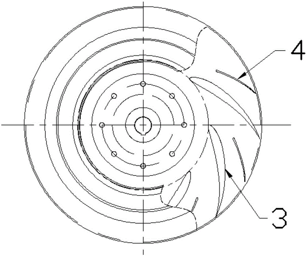
[0025] like figure 1 and 2 As shown, a centrifugal fan impeller with adjustable splitter blades includes a wheel disc 1 , a wheel cover 2 , main blades 3 , splitter blades 4 and a splitter blade adjustment device 5 . Between the wheel disc 1 and the wheel cover 2, n pieces of main blades 3 uniformly distributed along the circumference are fixedly arranged, n≥8; a splitter blade 4 is arranged between every two adjacent main blades 3; the splitter blade adjustment device 5 is used to adjust the splitter flow Blades 4 angles.

[0026] like image 3 As shown, the splitter vane adjusting device 5 includes a total fixed frame 5-1, a guide ring 5-2, a fixing device 5-3 on the splitter vane ring, a splitter vane adjustment member 5-4, and a fixing device 5 on the splitter vane wheel cover. -5 and the fixing device 5-6 on the splitter blade disc. The guide ...


PUM


Abstract

The invention discloses a centrifugal fan impeller capable of adjusting splitting vanes, and aims at solving the problems that the common working conditions of a current fan product in use do not match with the rated working conditions, thus the service efficiency of a fan is low, and the efficient operation range of the fan is reduced. The centrifugal fan impeller capable of adjusting the splitting vanes is characterized in that a circular guide ring and a wheel disc form a revolving pair; a main fixing frame which is provided with a circular guide ring fixing device is fixed to the wheel disc; the circular guide ring is connected to n upper fixing devices for the circular ring and the splitting vanes; the splitting vanes are connected to a wheel cover through upper fixing devices for the wheel cover and the splitting vanes, and the splitting vanes are connected with the wheel disc through upper fixing devices for the wheel disc and the splitting vanes; each upper fixing device for the circular ring and the splitting vanes is connected to the corresponding upper fixing device for the wheel disc and the splitting vanes through a splitting vane adjusting part. According to the centrifugal fan impeller, the circular guide ring can be rotated to drive the splitting vane adjusting parts to swing so as to adjust the angles of the splitting vanes, thus the maximum operation efficiency can be obtained according to different working conditions, and the maximum operation efficiency which can be achieved only under the rated working conditions can be obtained by a centrifugal fan under the off-rating conditions.

Description

technical field [0001] The invention belongs to the field of fan equipment and relates to a centrifugal fan, in particular to a centrifugal fan impeller with adjustable splitter blades. Background technique [0002] Energy is an important material basis for economic and social development and improvement of people's living standards. The energy issue is a crucial issue for a country. Since the 1990s, the contradiction between my country's energy supply and demand has been increasing, and the problem of energy shortage has emerged. According to the survey, wind turbines account for about 10% of the country's electricity consumption. The country requires that the efficiency of the fan should not be lower than 70%, but the average operating efficiency of the existing fan is only 40%-60%. It can be seen that the energy-saving potential of the fan is very considerable. Optimizing the performance of the fan, improving the operating efficiency, and enhancing the stability of the ...

Claims


Application Information

Patent Timeline
Patent Type & Authority Applications(China)
IPC IPC(8): F04D29/28F04D29/66F04D29/46
Inventor 窦华书李哲弘武林张滨炜周小颖刘琳
Owner ZHEJIANG SCI-TECH UNIV
Learn More