electrical tools

A technology for electric tools and working heads, which is applied in the field of power tools and can solve the problems of difficult access of working heads, difficulty in penetration, and large size of electric wrenches.

Active Publication Date: 2017-04-19
NANJING CHERVON IND
View PDF5 Cites 0 Cited by
  • Summary
  • Abstract
  • Description
  • Claims
  • Application Information

AI Technical Summary

Problems solved by technology

However, in the existing electric wrenches, there is usually only one working state, that is, the working head can only be in a fixed position. For some electric wrenches, on the one hand, the working head of the electric wrench is on the same axis as the main machine, which makes the electric wrench larger and difficult to penetrate into narrow areas; on the other hand, for areas that require turning to operate, the working head is difficult Access to the area to be operated

Method used


Image

  • electrical tools
  • electrical tools
  • electrical tools

Examples


Embodiment Construction

[0023] The present invention will be specifically introduced below in conjunction with the accompanying drawings and specific embodiments.

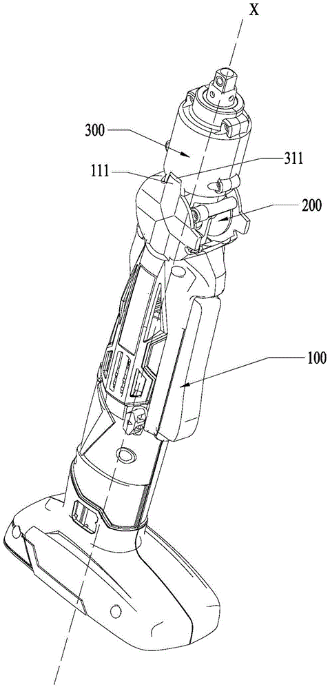
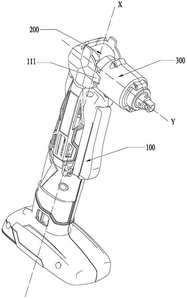
[0024] The present invention proposes an electric tool with multiple working states. The electric tool of the present invention can be various commonly used electric tools, such as electric drill, impact drill, electric wrench, etc. In this embodiment, an electric wrench is taken as an example. figure 1 Shown is a schematic structural view of a preferred embodiment of the electric tool of the present invention; figure 2 shown as figure 1 Schematic diagram of the structure of the electric tool in another working state. Please also refer to figure 1 with figure 2 , in this embodiment, the electric tool (not shown) is an electric wrench, which includes a host 100, a rotating housing 200, and a working head 300 connected to the host 100 through the rotating housing 200, through which the rotating housing The body 200 makes the working h...


PUM


Abstract

The invention discloses an electric tool. The electric tool comprises a main machine and a working head, wherein the working head relative to the main machine at least comprises more than two working stations, including a first working station and a second working station; the main machine comprises a main housing, a motor and a power assembly; the power assembly comprises a power shaft. The electric tool further comprises a rotating housing, which enables the working head to rotate relative to the main machine along with the rotating housing; the working head comprises a head part housing, a driving assembly and an output head; the driving assembly comprises a driving shaft; a first transmission mode which is used when the working head is at the first working station, and a second transmission mode which is used when the working head is at the second working station, are arranged between the power shaft and the driving shaft; the head part housing is in slide connection with the rotating housing; when sliding relative to the rotating housing, the head part housing is at least provided with a first slide station and a second slide station. The electric tool comprises at least two working states, namely, the working state which is used when the working head is at the first working station, and another working state which is used when the working head is at the second working station.

Description

technical field [0001] The invention relates to a power tool, in particular to a power tool with a rotatable working head. Background technique [0002] The electric wrench includes a working head and a host part, and it is used as a tool for tightening screws through electric drive, and is widely favored by users. However, in the existing electric wrenches, there is usually only one working state, that is, the working head can only be in a fixed position. For some electric wrenches, on the one hand, the working head of the electric wrench is on the same axis as the main machine, which makes the electric wrench larger and difficult to penetrate into narrow areas; on the other hand, for areas that require turning to operate, the working head is difficult access to the area to be operated. Contents of the invention [0003] In order to solve the deficiencies of the prior art, the object of the present invention is to provide an electric tool with a rotatable working head. ...

Claims


Application Information

Patent Timeline
Patent Type & Authority Patents(China)
IPC IPC(8): B25B21/00B25F5/02B25F5/00
Inventor 章利进塞韦里茨·格奥尔基
Owner NANJING CHERVON IND
Why Eureka
Try Eureka