
Multi-channel linear floor drain

A linear, multi-channel technology, applied in waterway systems, indoor sanitary piping installations, climate change adaptation, etc., can solve problems such as sanitary personnel stumbling, wasting pipeline resources, increasing construction volume, etc., to achieve less water accumulation, The effect of simplifying work and speeding up drainage

Inactive Publication Date: 2016-02-03
FUZHOU KEME ENERGY SAVING TECH
View PDF5 Cites 2 Cited by
  • Summary
  • Abstract
  • Description
  • Claims
  • Application Information

AI Technical Summary

Problems solved by technology

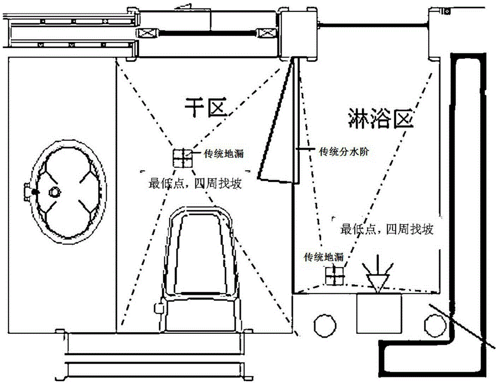
[0002] In the traditional bathroom space, two floor drains are usually required, which are used for the dry area and the wet area respectively. The wet area of ​​the dry area is separated by water-retaining strips or O-grooves to separate water, which not only wastes pipeline resources, but also increases the amount of construction. , and because the water retaining strip protrudes from the ground, it is easy to cause staggering to the bathroom personnel and affect the safety
In the selection of household drainage floor drains, the current silicone floor drains are popular with consumers because of their easy installation, fast water discharge, and good deodorization capabilities. In comparison, the metal deep water seal is not afraid of rat bites, but because the deep water seal uses its internal water storage to deodorize, if the water storage dries up, the deep water seal cannot deodorize

Method used


Image

  • Multi-channel linear floor drain
  • Multi-channel linear floor drain
  • Multi-channel linear floor drain

Examples


Embodiment

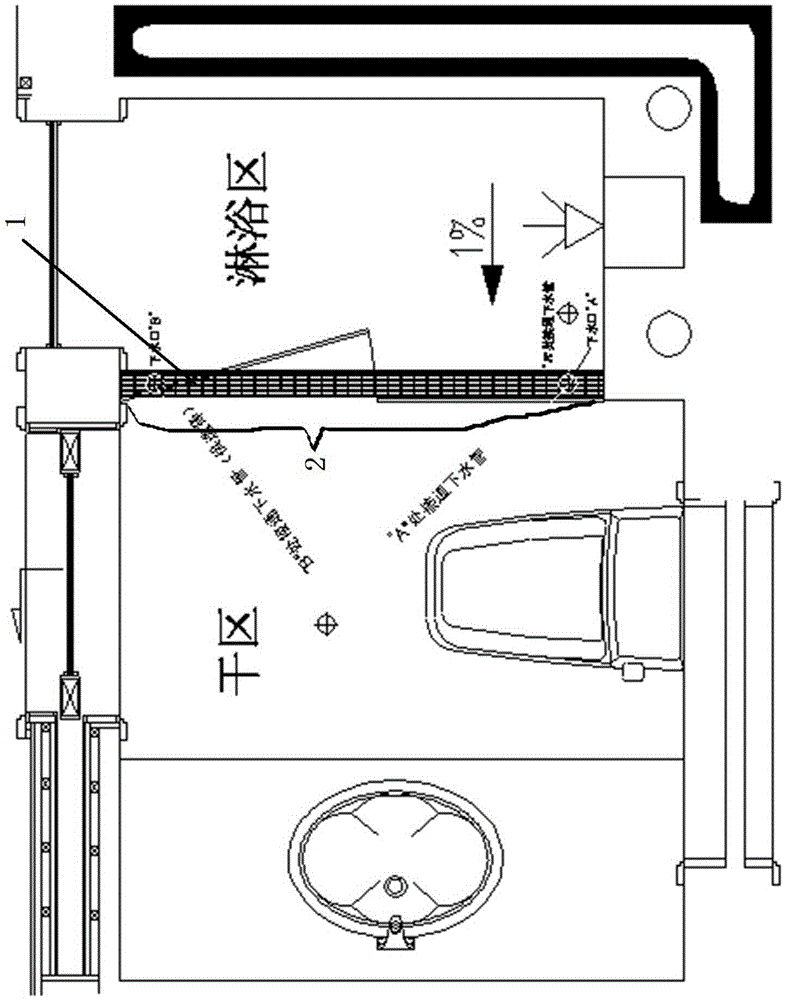
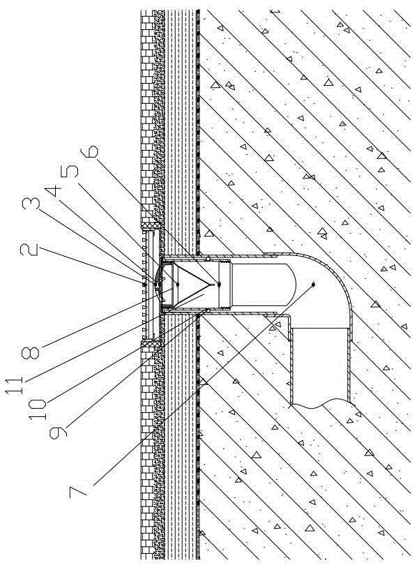
[0042] Such as figure 1 As shown, in the bathroom space, the floor drain is installed between the dry area and the wet area, and the confluence groove 4 is used as a separation part between the dry area and the wet area. The water in the dry area and the wet area can flow into the floor drain downpipe through the confluence groove 4 , when draining, the silicone membrane of the silicone seal 5 opens, and the water passes through the silicone seal 5 and the deep water seal 6 in sequence before flowing into the external drain pipe 7. After the drainage is completed, the silicone membrane is completely closed under the action of its own elasticity, forming The first water-passing sealing layer, when water flows through the deep water seal, will form the second water-passing sealing layer through the water seal deodorization mechanism in the deep water seal 6, thereby strengthening the deodorizing effect.

[0043] When the floor drain is not in use for a long time, the first water...


PUM


Abstract

The invention discloses a multi-channel linear floor drain. The multi-channel linear floor drain comprises a grate, a conflux tank, floor drain downpipes, drain pipes, silica gel sealing parts, deepwater seals and sealing rings. The floor drain downpipes are installed at the bottom of the conflux tank. Upper ports of the floor drain downpipes are formed in the end face of the bottom of the conflux tank and covered with filter nets. Lower ports of the floor drain downpipes are connected with the drain pipes. The silica gel sealing parts and the deepwater seals are sequentially arranged in water falling channels formed by the floor drain downpipes and the drain pipes from top to bottom to form two water passing sealed layers, and the silica gel sealing parts are located above the deepwater seals. A conflux structure is integrated on the floor drain, the dry area and the wet area of bathroom space can achieve the dry and wet separation function under the condition of sharing the floor drain, the ground is attractive after completion of work, and the workload of slope finding in the traditional floor drain installing process is omitted. According to the structure, the silica gel sealing parts are additionally arranged on the deepwater seals, the deordorization function of the floor drain is more lasting, and a good ratproof effect is achieved.

Description

technical field [0001] The invention relates to drainage equipment, in particular to a multi-channel linear floor drain. Background technique [0002] In the traditional bathroom space, two floor drains are usually required, which are used for the dry area and the wet area respectively. The wet area of ​​the dry area is separated by water-retaining strips or O-grooves to separate water, which not only wastes pipeline resources, but also increases the amount of construction. , and because the water retaining strip protrudes from the ground, it is easy to cause stumbling and affect the safety of the bathroom personnel. In the selection of household drainage floor drains, the current silicone floor drains are popular with consumers because of their easy installation, fast water discharge, and good deodorization capabilities. In comparison, the metal deep water seal is not afraid of rat bites, but because the deep water seal uses its internal water storage to deodorize, if the ...

Claims


Application Information

Patent Timeline
IPC IPC(8): E03F5/04E03F7/06E03C1/298
CPCY02A30/60
Inventor 蔡品登
Owner FUZHOU KEME ENERGY SAVING TECH
Learn More