Eureka AIR delivers breakthrough ideas for toughest innovation challenges, trusted by R&D personnel around the world.

Coaxial cable shielding efficiency test dedicated load connector

A shielding efficiency, coaxial technology, applied in the direction of connection, two-part connection device, parts of the connection device, etc., can solve problems such as inability to connect cables, inability to connect loads, inconvenience, etc., to achieve convenient testing and testing. Accurate results and good shielding efficiency

Active Publication Date: 2018-04-17
SHENZHNE DNS IND CO LTD
View PDF4 Cites 0 Cited by
  • Summary
  • Abstract
  • Description
  • Claims
  • Application Information

AI Technical Summary

Problems solved by technology

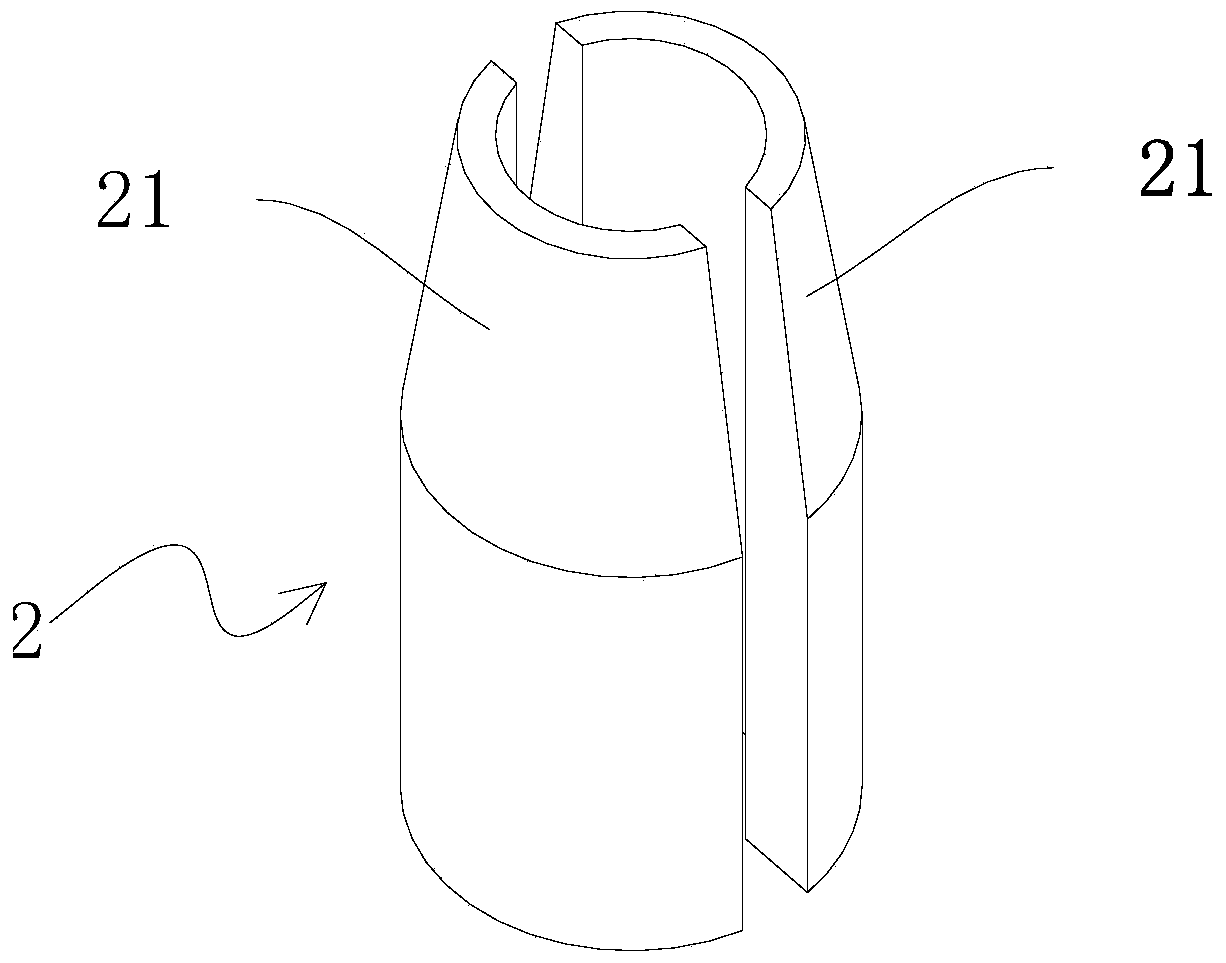
For the laboratory measurement of the transfer impedance and shielding attenuation effect of the coaxial cable, a network analyzer is used to connect the two ends of the cable to be tested for measurement, and in order to reduce the interference of the external environment on the coaxial cable, the test The result is accurate and shows the data of the coaxial cable itself purely. The coaxial cable to be tested is placed in the coupling tube 1 to measure the isolated external environment (such as figure 1 As shown), the two ends of the coupling tube 1 have terminals connected to the two ends of the coaxial cable, and the rear terminal 11 is the data input terminal. It is necessary to connect the load at the rear terminal 11 first, and then connect the Cable joints, the structure of the existing connection cable joints is as follows figure 2 The original connection terminal 2 shown is two halves that are vertically split in half. After being assembled, they are approximately cylindrical and hollow. The hollow part is a cylindrical through-hole structure, and cables can be clamped in the through-hole. The original The upper part of the connecting terminal 2 after splicing is the socket part 21, and the socket part 21 is a circular platform structure. When in use, the cable is clamped, and the socket part 21 is inserted into the rear terminal 11. This connection method The load cannot be connected, and the cable with the connector can not be connected, which is very inconvenient
There is no connection structure that can connect the load and be well connected with the cable joint

Method used


Image

  • Coaxial cable shielding efficiency test dedicated load connector
  • Coaxial cable shielding efficiency test dedicated load connector
  • Coaxial cable shielding efficiency test dedicated load connector

Examples


Embodiment Construction

[0015] The specific implementation manners of the present invention will be further described in detail below in conjunction with the accompanying drawings.

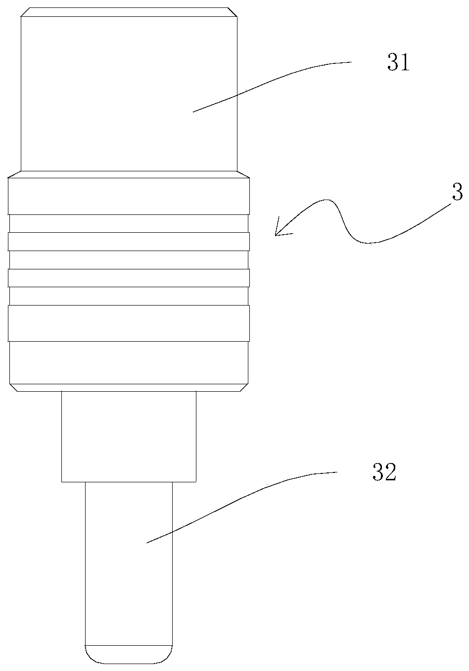
[0016] like figure 1 As shown in -3, in order to have a good shielding efficiency effect after the connection between the cable plug and the rear port 11 is loaded, so that the test value is more accurate, a special on-load connector for the coaxial cable shielding efficiency test of the present invention , including a cylindrical outer conductor 3, a central pin 4 is provided at the central axis of the outer conductor 3, an insulator 5 is provided between the central pin 4 and the outer conductor 3, and the upper part of the outer conductor 3 is a cable insertion part 31 , and the lower part of the outer conductor 3 is a metal tail pipe 32, the inner diameter of the metal tail pipe 32 is smaller than the inner diameter of the upper and middle parts of the outer conductor 3, and the insulator 5 is located in the middle o...


PUM


Abstract

A load-carrying connector for testing coaxial line shielding efficiency comprises a cylindrical outer conductor (3). A center pin (4) is disposed at the position of the central axis inside the outer conductor (3). The upper part of the outer conductor (3) is a cable plugging portion (31), and the lower part of the outer conductor (3) is a metal tail pipe (32). The bottom end of the center pin (4) is connected to a load and is disposed in the metal tail pipe (32). The internal part of the metal tail pipe (32) is sealed by metal. A shielding housing (6) having threads on the outer surface sleeves the metal tail pipe (32). One end of the load is connected to the center pin (4), and the other end of the load is connected to the outer conductor (3). The load-carrying connector for testing coaxial line shielding efficiency has one end capable of being plugged with a cable plug and the other end capable of being plugged or threadedly connected to a rear port; the testing is convenient, no extra load needs to be connected, and the shielding efficiency and effect are good.

Description

technical field [0001] The invention relates to the field of cable testing equipment, in particular to a special tape-loaded connector used in a coupling tube for testing the shielding efficiency of a coaxial line. Background technique [0002] The coaxial line is a common signal transmission line. The copper core in the center transmits high level and is covered by insulating material; Shielding effect. For the laboratory measurement of the transfer impedance and shielding attenuation effect of the coaxial cable, a network analyzer is used to connect the two ends of the cable to be tested for measurement, and in order to reduce the interference of the external environment on the coaxial cable, the test The result is accurate and shows the data of the coaxial cable itself purely. The coaxial cable to be tested is placed in the coupling tube 1 to measure the isolated external environment (such as figure 1 As shown), the two ends of the coupling tube 1 have terminals connect...

Claims


Application Information

Patent Timeline
Patent Type & Authority Patents(China)
IPC IPC(8): H01R13/648H01R13/66H01R24/38
CPCH01R13/648H01R13/66H01R24/38
Inventor 张小宇李秋实
Owner SHENZHNE DNS IND CO LTD
Why Eureka
Eureka Blog
Learn More