A usb Type‑C connector

An integrated, connecting part technology, applied in the field of USB connectors, can solve the problems of short service life of USB Type-C connectors, thick USB Type-C connectors, single shape of shielding shell, etc., achieve rich and beautiful appearance, reduce assembly processes, and improve resistance The effect of the ability to jam the signal

Inactive Publication Date: 2018-01-16
珠海中广视讯科技有限公司 +1
View PDF7 Cites 3 Cited by
  • Summary
  • Abstract
  • Description
  • Claims
  • Application Information

AI Technical Summary

Problems solved by technology

[0002] The USB connector is a commonly used electronic device, but the traditional USB Type-C connector has the following deficiencies: 1. The shielding structure of the traditional USB Type-C connector is made by bending and welding the hardware, and the formed shielding shell will There are welds, which belong to the seamed structure, the manufacturing process is complicated, the assembly process is many, and the cost is high; 2. The traditional USB Type-C connector only has a shielding shell that is welded after bending the hardware outside the terminal assembly, and the effect of shielding interference signals is relatively low. Poor; 3. The shielding shell of the traditional USB connector is welded by bending the hardware, the structural strength is poor, and the service life of the USB Type-C connector is short; 4. The shielding shell of the traditional USB Type-C connector is bent by the hardware It is folded and welded, which makes the thickness of the USB Type-C connector thicker, which cannot meet the user's pursuit of smaller and ultra-thin requirements; 5. The shielding shell of the traditional USB Type-C connector is welded by bending the hardware , due to the limitations of the process, the shape of the shielding shell is single, and it is impossible to produce more varied and more beautiful connectors

Method used


Image

  • A usb Type‑C connector
  • A usb Type‑C connector
  • A usb Type‑C connector

Examples


Embodiment Construction

[0023] The present invention will be further described below in conjunction with accompanying drawing:

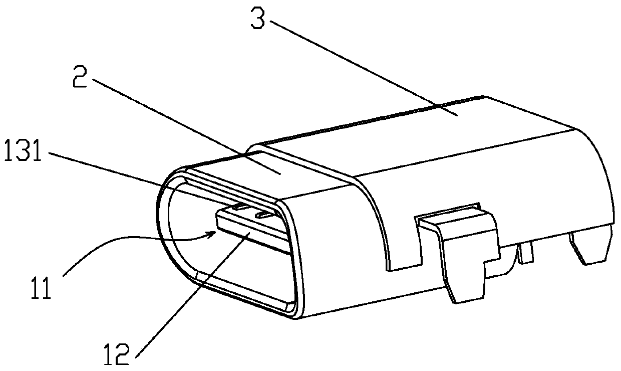
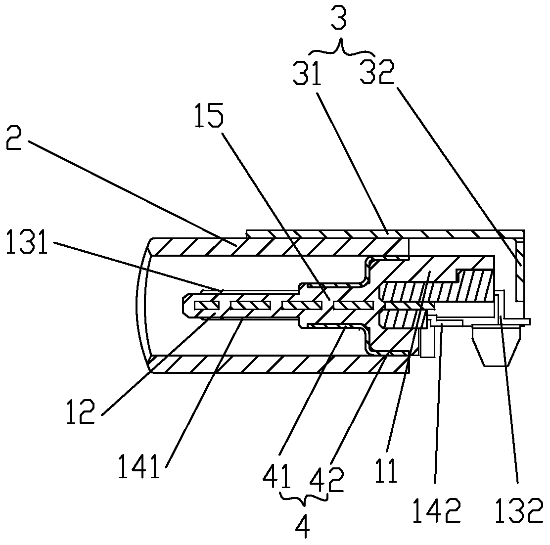
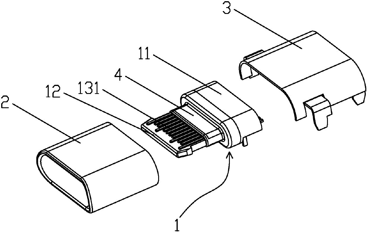
[0024] Such as figure 1 , figure 2 and Figure 5 As shown, a USB Type-C connector includes a terminal assembly 1. The terminal assembly 1 includes an insulating seat body 11, and the insulating seat body 11 is provided with a tongue plate 12 integrally formed with it and protruding forward. , the insulating base 11 is provided with an upper row of PIN needles 13 and a lower row of PIN needles 14 that are injection molded into one body and separated from each other. The upper row of PIN needles 13 includes an upper The front part 131 of the row of PIN needles and the rear part 132 of the upper row of PIN needles exposed on the insulating seat body 11, the described lower row of PIN needles 14 includes the front part 141 of the lower row of PIN needles exposed on the lower side of the tongue plate 12 and the rear part of the row of PIN needles exposed on the insulating sea...


PUM


Abstract

The invention discloses a USB Type-C connector, which includes a terminal assembly. The terminal assembly includes an insulating base body. The insulating base body is provided with a tongue plate, an upper row of PIN needles and a lower row of PIN needles. The upper row of PIN needles includes The front part of the upper row of PIN needles on the upper side of the board and the rear part of the upper row of PIN needles exposed on the insulating seat body, the lower row of PIN needles include the front part of the lower row of PIN needles exposed on the lower side of the tongue plate and the lower row of PIN needles exposed on the insulating seat body The rear part of the row of PIN pins is connected to the insulating seat body with an integrated seamless tubular front shielding shell. The tongue plate, the front part of the upper row of PIN pins and the front part of the lower row of PIN pins extend into the front shielding shell. It is also connected with the rear shielding shell which is riveted or laser welded to form a complete shielding shell, and the rear part of the insulating base body, the rear part of the upper row of PIN pins and the rear part of the lower row of PIN pins extend into the rear shielding shell. The invention has simple structure, low cost, high structural strength and long service life.

Description

【Technical field】 [0001] The invention relates to a USB connector, more specifically to a USB Type-C connector. 【Background technique】 [0002] The USB connector is a commonly used electronic device, but the traditional USB Type-C connector has the following deficiencies: 1. The shielding structure of the traditional USB Type-C connector is made by bending and welding the hardware, and the formed shielding shell will There are welds, which belong to the seamed structure, the manufacturing process is complicated, the assembly process is many, and the cost is high; 2. The traditional USB Type-C connector only has a shielding shell that is welded after bending the hardware outside the terminal assembly, and the effect of shielding interference signals is relatively low. Poor; 3. The shielding shell of the traditional USB connector is welded by bending the hardware, the structural strength is poor, and the service life of the USB Type-C connector is short; 4. The shielding shell...

Claims


Application Information

Patent Timeline
Patent Type & Authority Patents(China)
IPC IPC(8): H01R13/504H01R13/516H01R13/648
Inventor 沈全寿汪恩浩
Owner 珠海中广视讯科技有限公司
Why Eureka
Try Eureka