


Quick Research
Generate reliable direction feasibility study reports for your R&D in just a few steps.

Technical Q&A
Discover and master advanced knowledge NOW. Basics, ideas, possibilities, all at once.

Find Solutions
As an expert in R&D theories, this can generate solutions to your technical problems instantly.

Evaluate Feasibility
Analyze your overall solution with one click, know your potential R&D risks in advance.

Monitor Landscape
Get weekly tech updates, stay abreast of the latest tech innovations and key insights.
Work stop
A technology of stopper and workpiece, applied in the direction of conveyor objects, transportation and packaging, etc., can solve the problems of scratches and inability to fully absorb shocks, etc.
- Summary
- Abstract
- Description
- Claims
- Application Information
AI Technical Summary
Problems solved by technology
Method used
Image

Examples
Embodiment 1
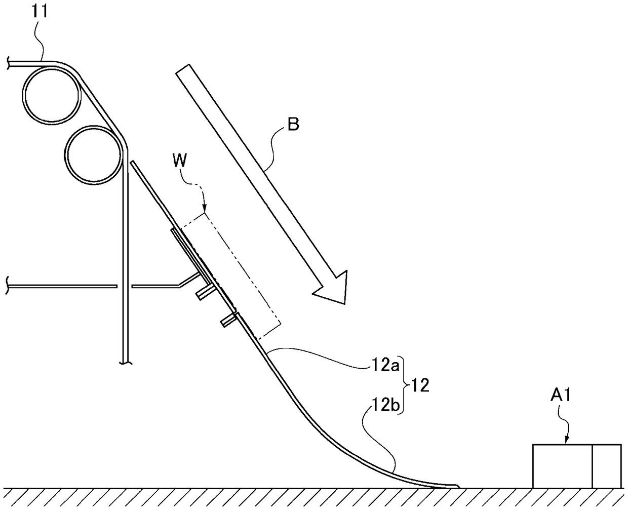
[0041] First, based on figure 1 The configuration of a gear production line for an automatic transmission to which the work stopper device A1 of the first embodiment is applied will be described.
[0042] In the gear manufacturing line of automatic transmission, such as figure 1 As shown, a gear member W (an example of a circular workpiece) immediately after being heated in a furnace for heat treatment is conveyed by falling down the chute of the workpiece conveyance path 1 based on the conveyor belt 11 and the slide plate 12 . The setting angle of the workpiece conveying path 1 formed by the conveying belt 11 and the straight path 12a of the slide plate 12 is formed at a steep angle of more than 55 degrees, for example, with little space. The slide plate 12 has a curved path 12b continuous with the straight path 12a, and the horizontal end position of the curved path 12b is set as a workpiece stop position.
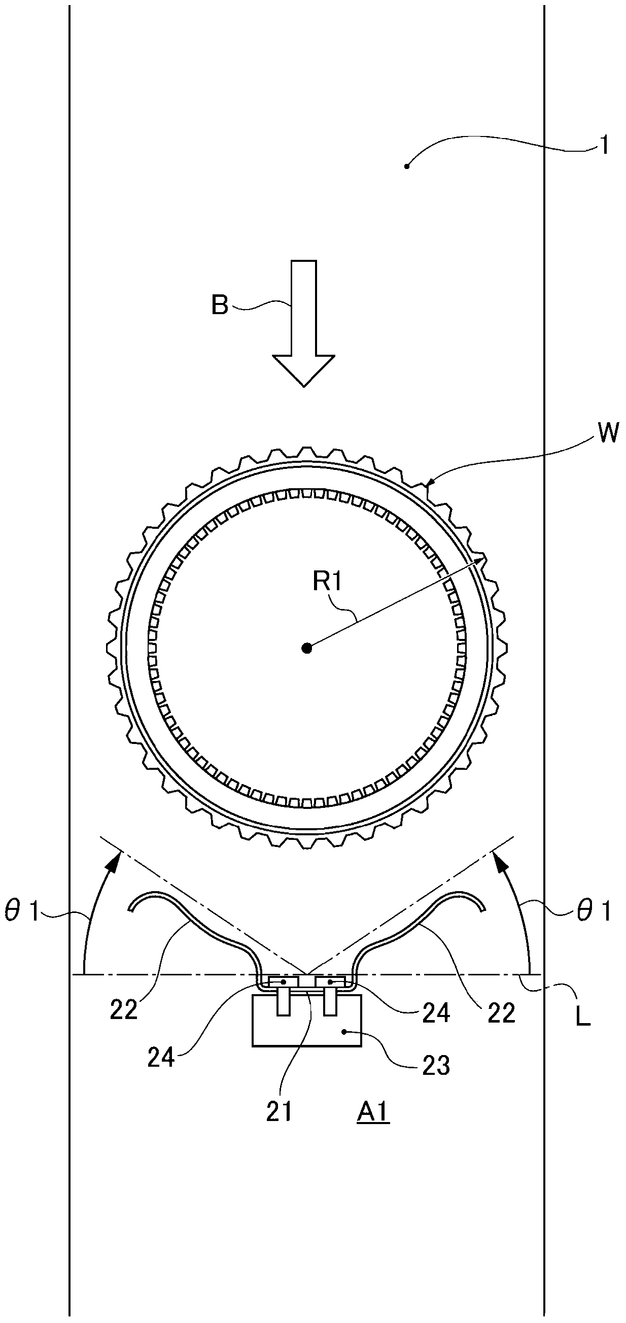
[0043] The workpiece stopper A1 is arranged at the workpiece stop...
Embodiment 2
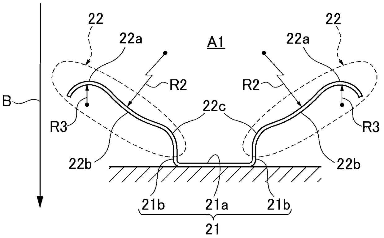
[0064] Embodiment 2 is a modified example in which the shapes of the pair of extensions 22 and 22 are different from those of Embodiment 1. As shown in FIG.
[0065] based on Figure 4 The structure of the pair of extension parts 22 and 22 in the work stopper A2 of Example 2 is demonstrated.
[0066] The pair of extensions 22 and 22 of the second embodiment extend in a substantially V-shape in the oblique direction from both sides of the base 21 fixed to the block 23 , and contact the gear member W to stop it. The inclination angles θ2 and θ2 of the pair of extensions 22 and 22 are formed to be angles that act 60 degrees from both sides of the line L in the direction perpendicular to the workpiece conveyance direction B to the travel direction B of the component. That is, the opening angle of the V shape of the blocker gear member W is set to about 60 degrees.
[0067] The pair of extension parts 22, 22 has first curved parts 22a', 22a' on the outer side of the part where th...
PUM
 Abstract
Description
Claims
Application Information
 - R&D Engineer
- R&D Manager
- IP Professional
- Industry Leading Data Capabilities
- Powerful AI technology
- Patent DNA Extraction
Browse by: Latest US Patents, China's latest patents, Technical Efficacy Thesaurus, Application Domain, Technology Topic, Popular Technical Reports.
© 2024 PatSnap. All rights reserved.Legal|Privacy policy|Modern Slavery Act Transparency Statement|Sitemap|About US| Contact US: help@patsnap.com