CSI-RS port mapping method and device
A technology of port mapping and port, which is applied in the field of CSI-RS port mapping method and device, and can solve problems such as increasing the complexity of system design
- Summary
- Abstract
- Description
- Claims
- Application Information
AI Technical Summary
Problems solved by technology
Method used
Image
Examples
Embodiment 1
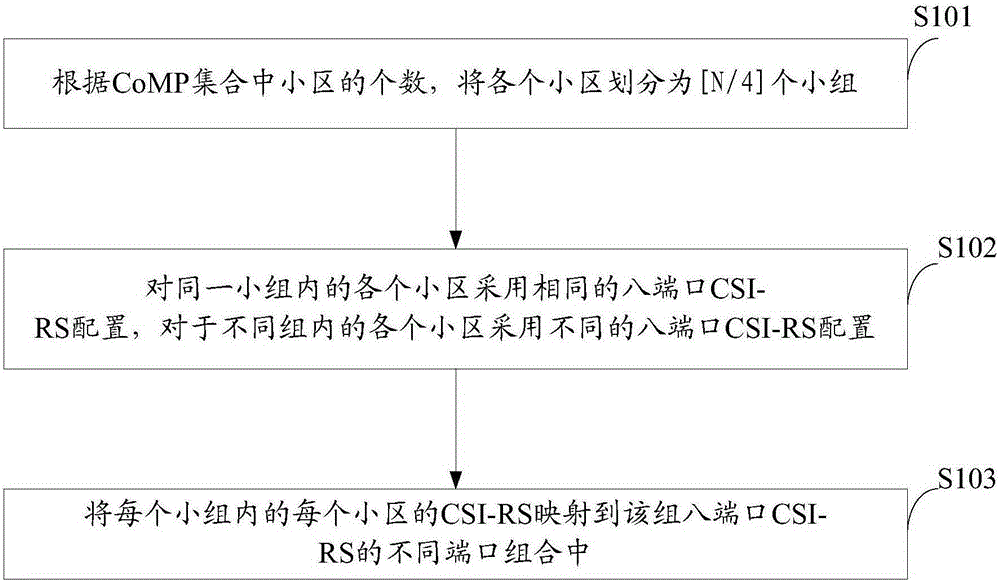
[0041] see figure 1 It shows a schematic flowchart of a CSI-RS port mapping method in the present invention. The method described in this embodiment is specifically applied to a cell supporting eight-antenna and two-port transmission, including:
[0042] S101: According to the number of cells in the CoMP set, divide each cell into group.
[0043] Where N represents the number of cells in the CoMP set, Indicates rounding up. It can be understood that when the number of cells is greater than or equal to 1 and less than or equal to 4, all the cells are divided into the same group, and when the number of cells is greater than 4 and less than or equal to 8, the cells are divided into two cells.
[0044] S102: Adopting the same eight-port CSI-RS configuration for each cell in the same group, and adopting a different eight-port CSI-RS configuration for each cell in a different group.
[0045]The CSI-RS can support a maximum of 8 logical ports, and in this embodiment, the CSI-R...
Embodiment 2
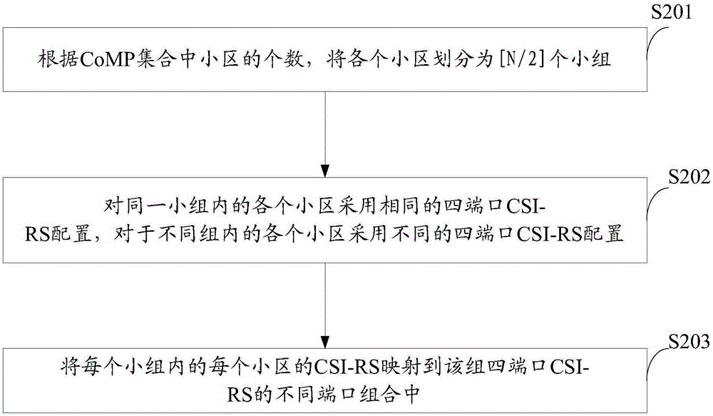
[0053] see figure 2 A schematic flowchart of a CSI-RS mapping method disclosed in another embodiment of the present invention is shown. Compared with Embodiment 1, the method disclosed in this embodiment is also applicable to a cell with eight antennas and two ports for transmission. The difference is that the CSI-RS configuration in this embodiment adopts 4-port CSI configuration.
[0054] The specific process is as follows:
[0055] S201: According to the number of cells in the CoMP set, divide each cell into groups, where N represents the number of cells in the CoMP set, Indicates rounding up;
[0056] S202: adopting the same four-port CSI-RS configuration for each cell in the same group, and adopting a different four-port CSI-RS configuration for each cell in a different group;
[0057] S203: Map the CSI-RS of each cell in each group to different port combinations of the four-port CSI-RS group, where the port combination is a 2-port port combination.
Embodiment 3
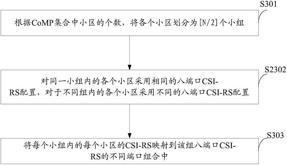
[0059] Optionally, the realization principle of the foregoing method may also be applied to a cell supporting eight-antenna and four-port transmission. see image 3 A schematic flowchart of a CSI-RS mapping method disclosed in another embodiment of the present invention.
[0060] S301: According to the number of cells in the CoMP set, divide each cell into groups, where N represents the number of cells in the CoMP set, Indicates rounding up.
[0061] S302: Adopting the same eight-port CSI-RS configuration for each cell in the same group, and adopting a different eight-port CSI-RS configuration for each cell in a different group.
[0062] S303: Map the CSI-RS of each cell in each group to different port combinations of the eight-port CSI-RS group, where the port combination is a 4-port port combination.
PUM
 Abstract
Description
Claims
Application Information
 - R&D Engineer
- R&D Manager
- IP Professional
- Industry Leading Data Capabilities
- Powerful AI technology
- Patent DNA Extraction
Browse by: Latest US Patents, China's latest patents, Technical Efficacy Thesaurus, Application Domain, Technology Topic, Popular Technical Reports.
© 2024 PatSnap. All rights reserved.Legal|Privacy policy|Modern Slavery Act Transparency Statement|Sitemap|About US| Contact US: help@patsnap.com


