Stack-up connecting element, connector and connector group

A connector group and connector technology, applied in the direction of instruments, optical components, light guides, etc., can solve the problems of increased production cost, troublesome operation, poor versatility, etc., and achieve the effect of good versatility, convenient assembly, and easy assembly and replacement.

Active Publication Date: 2016-01-20
CHINA AVIATION OPTICAL-ELECTRICAL TECH CO LTD
View PDF8 Cites 3 Cited by
  • Summary
  • Abstract
  • Description
  • Claims
  • Application Information

AI Technical Summary

Problems solved by technology

[0003] This type of connector stacking connection has poor versatility, and it is necessary to select fastening posts of different lengths according to the number of stacked connectors, which increases the types of fastening posts and increases production costs. When continuing to stack the connectors on the upper side of the connector group, it is necessary to replace the fastening column as a whole and reinstall all the stacked connectors, which is very troublesome to operate

Method used


Image

  • Stack-up connecting element, connector and connector group
  • Stack-up connecting element, connector and connector group
  • Stack-up connecting element, connector and connector group

Examples


Embodiment Construction

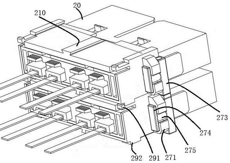
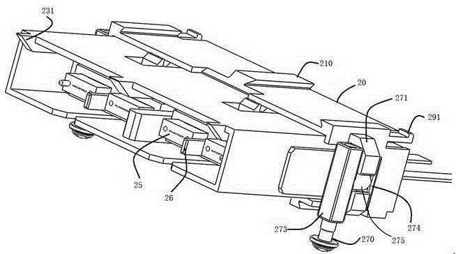
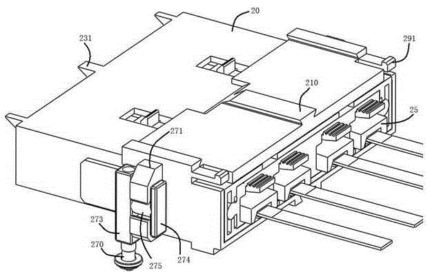
[0025] Embodiment 1 of the connector set of the present invention: as figure 1 As shown, it includes two connectors stacked up and down. In this embodiment, for the sake of illustration, only two connectors are stacked as an example. In other embodiments, the number of connectors can be three or three above. The structure of the connector is as Figure 2-9 As shown, it includes a rectangular connector housing 20 and a floating connection structure connecting the housing 20 and a fixed mounting plate. The stacking connector for fixing the mounting plate, the stacking connector includes a connecting column 273 extending up and down for connecting with the side of the connector housing 20, the upper end of the connecting column 273 is provided with an upper threaded hole 2732, the connecting column The lower end of the body is provided with a lower threaded hole 2731, and the connecting cylinder 273 connects the connector to the horizontal base plate through the screw connectio...


PUM


Abstract

The invention provides a stack-up connecting element, a connector and a connector group. The connector group comprises at least two connectors stacked up in an upper-lower mode; the connectors include connector housings and stack-up connecting elements arranged at the left and right sides of the connector housings; the stack-up connecting elements contains connecting cylinders that extend up and down and are connected with sides of the connector housings; and upper threaded holes or upper threaded cylinders are arranged at the upper ends of the connecting cylinders; lower threaded holes or lower threaded cylinders are arranged at the lower ends of the connecting cylinders. The connector arranged at the lower side between the two adjacent connectors is connected with the lower threaded holes or lower threaded cylinders at the lower end of the connecting cylinders corresponding to the connector arranged at the upper side by the corresponding upper threaded holes or upper threaded cylinders arranged at the upper end of the corresponding connecting cylinders. The stack-up connecting element has advantages of high universality and simple structure. With the stack-up connecting element, installation becomes convenient when multiple connectors are stacked up.

Description

technical field [0001] The invention relates to a stacked connector, a connector and a connector set. Background technique [0002] As a basic component of optical signal transmission, optical fiber connector plays a very important role in communication and information systems. The Chinese invention patent with the authorized announcement number CN1269271C and the authorized announcement date of August 9, 2006 discloses a floating installation system for a connector device. The floating installation system includes a connector housing, and the left and right sides of the connector housing are provided with A groove extending up and down perpendicular to the bottom plate. Two fastening posts are connected to the bottom plate by screws. The two fastening posts correspond to the two slots on the connector housing respectively. The connector housing connects the fastening posts and the slots At the same time, this document also discloses a connection form in which multiple conn...

Claims


Application Information

Patent Timeline
IPC IPC(8): G02B6/38
CPCG02B6/3897
Inventor 刘卫锋崔艳磊孙亚磊周生贺
Owner CHINA AVIATION OPTICAL-ELECTRICAL TECH CO LTD
Why Eureka
Try Eureka