
A ticket printing device

A printing device and ticket technology, applied in power transmission devices, printing, typewriters, etc., can solve the problems of inconvenient cleaning of the printing head, inability to guarantee the printing effect, and inability to easily open, etc., to achieve the effect of printing pressure balance

Active Publication Date: 2017-06-09
EASYWAY SUZHOU ELECTRONICS TECH
View PDF6 Cites 0 Cited by
  • Summary
  • Abstract
  • Description
  • Claims
  • Application Information

AI Technical Summary

Problems solved by technology

[0003] However, in this printing method, the pressure between the print head and the bill is fixed and there is no buffer. It is difficult to ensure that the print head is completely close to the entire bill face, especially for bills with problems on the face, the printing effect cannot be guaranteed.
[0004] Moreover, the existing ticket printing device is usually fixedly installed in the ticketing equipment, which cannot be easily opened, and is not convenient for cleaning the printing head.

Method used


Image

  • A ticket printing device
  • A ticket printing device
  • A ticket printing device

Examples


Embodiment Construction

[0022] The present invention will be further described below in conjunction with the accompanying drawings.

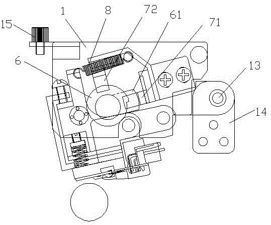
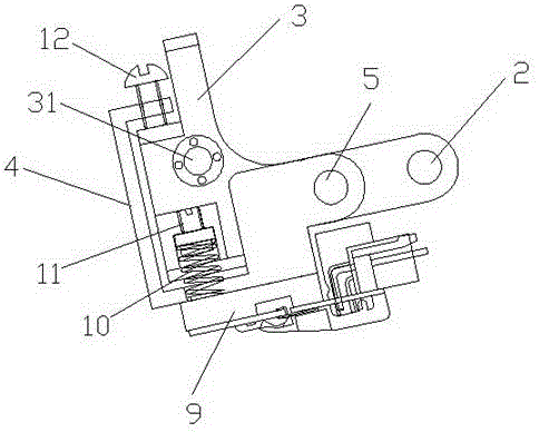
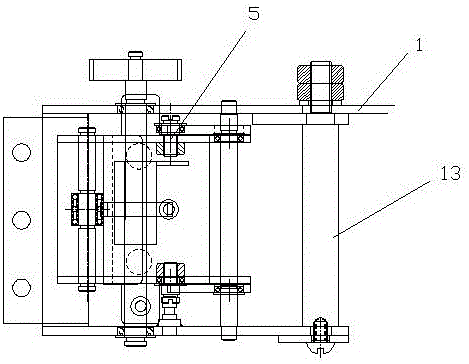
[0023] like Figure 1-Figure 4 As shown, a bill printing device includes two side plates 1, a first support plate 3 that can rotate relative to them is arranged between the two side plates 1, and a movable A rotatable eccentric wheel 6 is also arranged between the two side plates 1 along with the printing head 9 moving thereon, and a first rotating shaft 31 in contact with the eccentric wheel 6 is arranged on the first support plate 3 , A tension spring 8 is also provided between the upper end of the first support plate 3 and the side plate 1 .

[0024] When the bill to be printed reaches the bottom of the print head 9, the eccentric wheel 6 is controlled to rotate counterclockwise. During its rotation, the first rotating shaft 31 is squeezed by the eccentric wheel 6, and the first support plate 3 rotates counterclockwise, thereby driving the printing Head 9 presses ...


PUM


Abstract

The invention discloses a bill printing device which comprises two side plates. A first supporting plate capable of rotating relative to the two side plates is arranged between the two side plates. A printing head capable of rotating along with the first supporting plate is arranged below the first supporting plate. A rotatable eccentric wheel is arranged between the two side plates. The first supporting plate is provided with a first rotary shaft in contact with the eccentric wheel. Tension springs are arranged between the upper end of the first supporting plate and the side plates. The printing head is driven by the eccentric wheel to move downwards to achieve printing, printing pressure is adjusted through a pressure spring between the printing head and the supporting plate, balance is good, and the service life is long.

Description

technical field [0001] The invention relates to a bill printing device, which belongs to the technical field of bill printing. Background technique [0002] With the continuous advancement of technology, various self-service ticketing equipment are emerging, and the ticket printing module is an indispensable part of the self-service ticketing equipment. However, the existing printing module usually presses down the printing head directly to realize the receipt printing when the receipt reaches the designated position. [0003] However, in this printing method, the pressure between the print head and the bill is fixed and there is no buffer, so it is difficult to ensure that the print head is completely close to the entire face of the bill, especially for bills with problems on the face, the printing effect cannot be guaranteed. [0004] Moreover, the existing ticket printing device is usually fixedly installed in the ticketing equipment, which cannot be easily opened, and i...

Claims


Application Information

Patent Timeline
Patent Type & Authority Patents(China)
IPC IPC(8): B41J25/308B41J3/00
Inventor 庞明毕虎杰景大年
Owner EASYWAY SUZHOU ELECTRONICS TECH
Learn More