Audio Module Bonding Detector

A detector and audio technology, applied in the direction of line/collector components, electrical components, circuits, etc., can solve the problems of inflexible operation, affecting work efficiency, increasing cost and weight, etc., and achieve convenient and fast operation , The effect of convenient tangent operation

Active Publication Date: 2017-10-03
RES INST OF ECONOMICS & TECH STATE GRID SHANDONG ELECTRIC POWER +1
View PDF6 Cites 0 Cited by
  • Summary
  • Abstract
  • Description
  • Claims
  • Application Information

AI Technical Summary

Problems solved by technology

[0003] 1. Due to the existence of the cross arm 41', when placing the core wire into the wire clamp, it is necessary to first pass the core wire through the cross bars 41' on the left and right sides of the pressing block 4', which takes time to thread and affects work efficiency; moreover, the clamping The pliers need to be fixed with the pin shaft 313', and the setting of the pin shaft 313', the cross arm 41' and the fixed rod 42' increases the cost and weight of the whole device, and the setting makes the whole device appear cumbersome and inflexible in operation
[0004] 2. Due to the isolated setting of the blades, occasionally the blades will be bent or broken. Once one of the blades is bent or broken, the whole device cannot be used

Method used


Image

  • Audio Module Bonding Detector
  • Audio Module Bonding Detector
  • Audio Module Bonding Detector

Examples


Embodiment Construction

[0037] Specific embodiments of the present invention are described in detail below in conjunction with accompanying drawings:

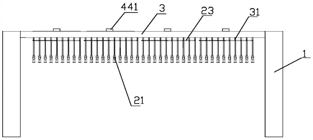
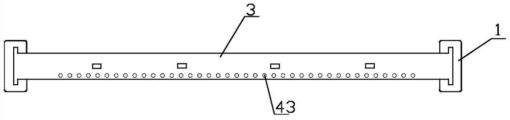
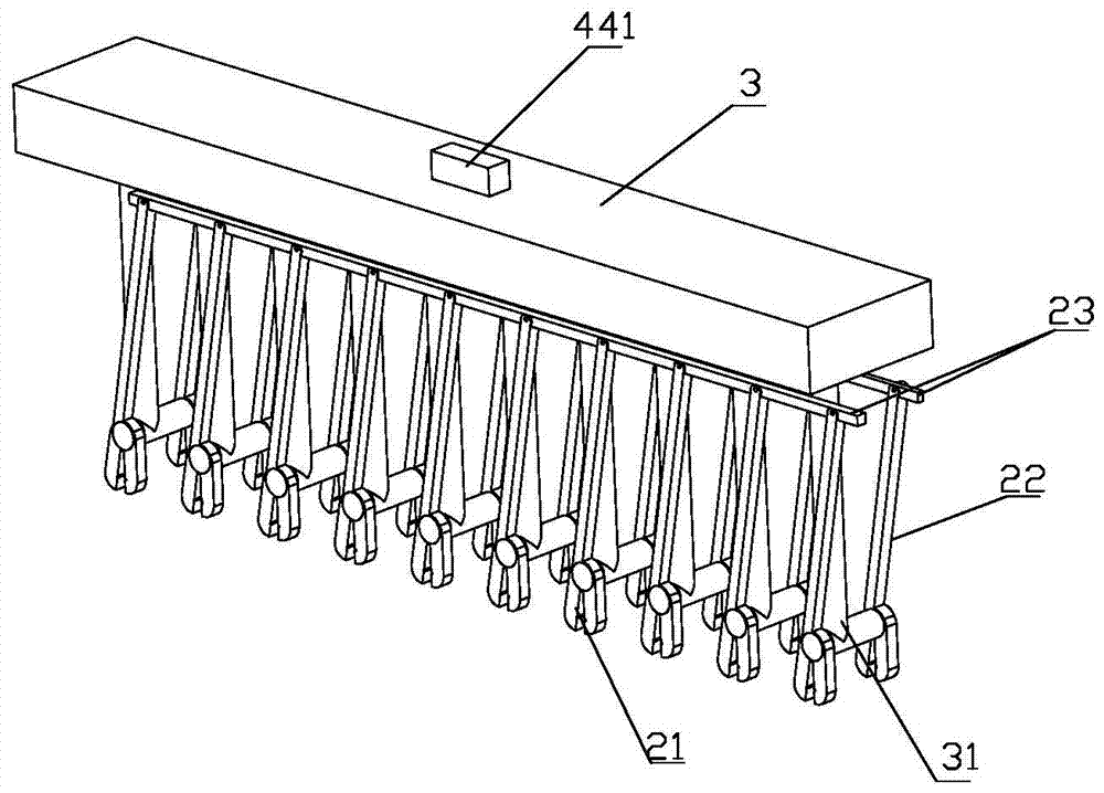
[0038] Such as Figure 1-Figure 10 As shown, the present invention includes a fixed frame 1, a first tensioner 2, a pressure block 3 and a detection device, the pressure block 3 is nested in the fixed frame 1, and the pressure block 3 can slide up and down in the fixed frame 1 , the detection device is arranged on the pressing block 3 . The inner side of the lower part of the fixed frame 1 is provided with engaging slots that cooperate with both sides of the audio module.

[0039] The first wire clamp 2 includes a wire clamp 21, a connecting rod 22 and a tie rod 23. The wire clamp 21 includes a pincer foot I 211 and a pincer foot II 212, which are oppositely arranged on the pincer foot I 211 and pincer foot II 212. There is a clamping groove 213. Preferably, after the clamp foot I 211 and the clamp foot II 212 are docked, the clamping groove on the ...


PUM


Abstract

The invention relates to an audio module wire bonding detector. The audio module wire bonding detector includes a fixing frame, a first wire clamping device, a pressing block and a detection device; the pressing block comprises T-shaped fixing rods; L-shaped pressing rods are arranged in the T-shaped fixing rods; blades and probes are respectively fixed at two ends of the bottom of each L-shaped pressing rod; a first cavity is arranged in the pressing block; pressure springs are arranged between the lower surface of a pressing plate and the pressing block; each pin shaft on the first wire clamping device is fixed to one end of the bottom of a corresponding T-shaped fixing rod; a wire clamping device is fixed at the other ends of the bottoms of the T-shaped fixing rods; a clamp pin I and a clamp pin II of the first wire clamping device are oppositely provided with slide grooves which extend from the pin shaft to positions below wire clamping grooves; and the blades are arranged in the slide grooves. The audio module wire bonding detector of the invention has the advantages of light structure, fast threading, no possibility of bending and fracturing the blades and capability of cutting core wires fast and neatly.

Description

technical field [0001] The invention relates to audio module wiring equipment, in particular to an audio module wiring detector. Background technique [0002] When the audio module is wired, the core wire needs to be clamped into the clamping hole. The current wiring method is to use a wiring knife to punch a single wire slot of the audio module, which is time-consuming and laborious. For this reason, our company has developed a "multifunctional audio crimping device", and has applied for invention and utility model patents at the same time. The application number for the invention patent is 2015105351738. Some of its structures are as follows Figure 11 and Figure 12 shown. After using it for a period of time, many operators reported that the device has the following problems: [0003] 1. Due to the existence of the cross arm 41', when placing the core wire into the wire clamp, it is necessary to first pass the core wire through the cross bars 41' on the left and right s...

Claims


Application Information

Patent Timeline
Patent Type & Authority Patents(China)
IPC IPC(8): H01R43/048
Inventor 王辉于昉张如杰侯源红刘海涛邵淑燕张雷刘晗王杰张慧
Owner RES INST OF ECONOMICS & TECH STATE GRID SHANDONG ELECTRIC POWER
Why Eureka
Try Eureka