Door lock of roller shutter door and working principle of door lock
A rolling door and rolling door motor technology, which is applied in the field of rolling doors, can solve the problems of manual unlocking, rolling doors without special door lock devices, and cumbersome operation steps, and achieve the effect of saving installation costs
- Summary
- Abstract
- Description
- Claims
- Application Information
AI Technical Summary
Problems solved by technology
Method used
Image
Examples
Embodiment 1
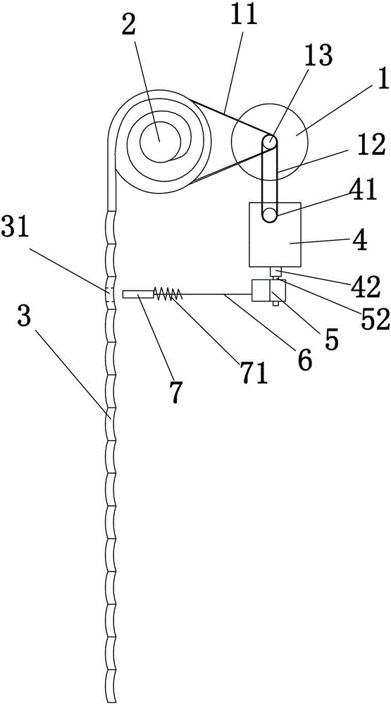
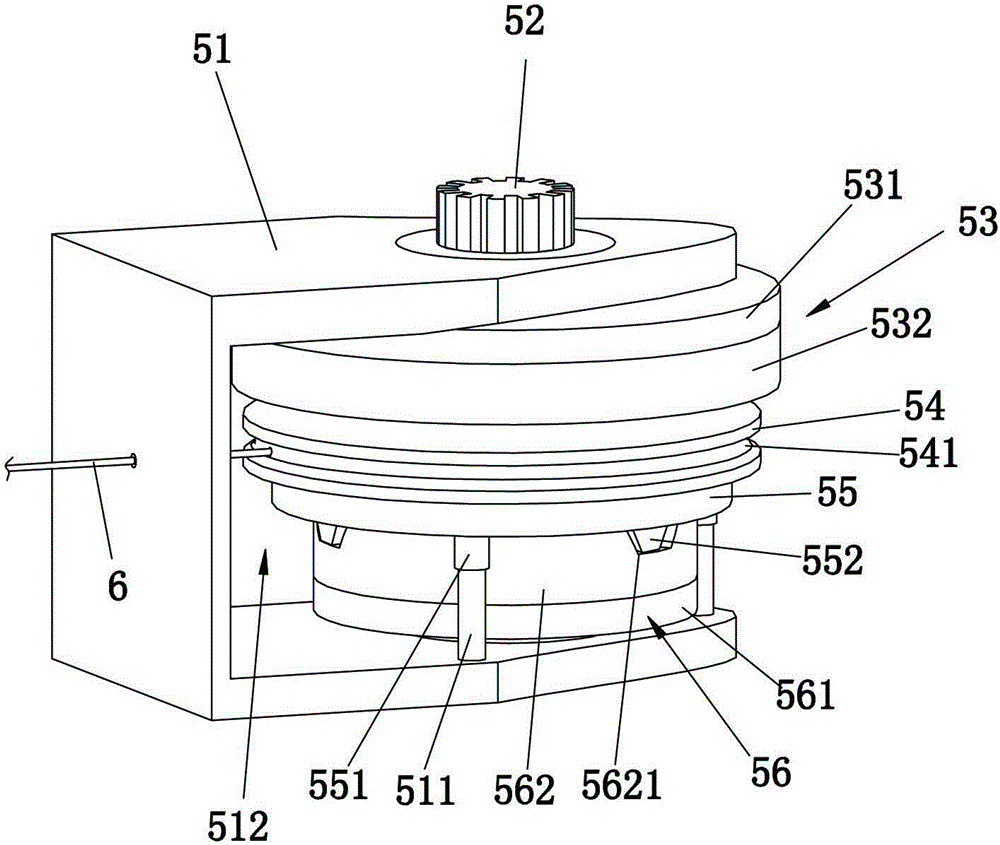
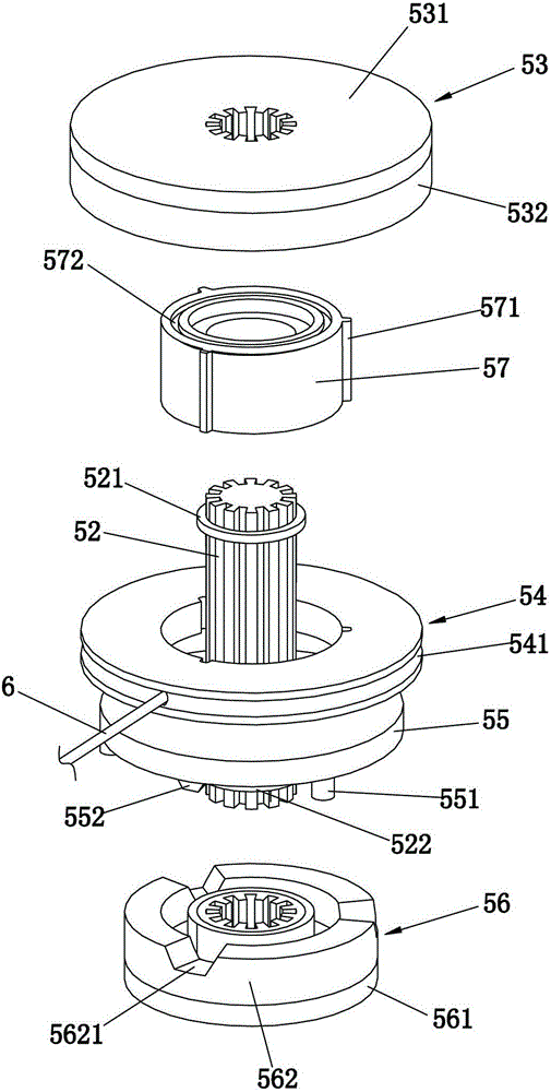
[0029] refer to Figure 1 to Figure 4 , the rolling door lock, including a lock core 7 and a spring 71 that moves the lock core 7 toward the rolling door 3 and locks the rolling door 3 . The shutter door lock also includes a cable 6, a clutch device 5 and a motor, wherein the clutch device includes a frame body 51, a rotating shaft 52, a first damping wheel 53, a winding wheel 54, a second damping wheel 56, a return spring (not shown in the figure) Out), disc 55 and chuck 57. One end of the cable 6 is connected to the lock cylinder 7 , and the other end is detachably connected to the reel 54 through the through hole in the annular recess 541 . The lock cylinder 7 is a straight rod slidably arranged along its length direction, and the rolling shutter door 3 is provided with a socket 31 matched with the lock cylinder 7 .
[0030] refer to Figure 2 to Figure 4 , the frame body 51 is U-shaped and forms a mounting groove 512 , and at least one cylinder 511 is disposed in the mo...
Embodiment 2
[0041] refer to Figure 5 , the rolling door lock includes a rolling door motor 1 , an acceleration box 4 , a clutch device 5 , a cable 6 , a spring 71 and a lock cylinder 7 . Regarding the specific setting method of the lock core 7, another specific embodiment: the rolling door lock also includes a supporting block 10, a bracket 8 and at least one connecting rod 9, and the lock core 7 is provided with a curved surface that matches the inner concave surface 32 of the rolling door 3 72. One end of the connecting rod 9 is pivotally connected to the bracket 8 , and the other end is pivotally connected to the lock cylinder 7 , and the lock cylinder 7 is located obliquely below the bracket 8 . The supporting block 10 is supported on the outer surface of the rolling door 3 and cooperates with the lock cylinder 7 to clamp the rolling door 3 . When a thief uses a tool to try to pry open the rolling door 3, since the lock core 7 is arranged on the oblique lower side of the support 8 ...
PUM
 Abstract
Description
Claims
Application Information
 - R&D
- Intellectual Property
- Life Sciences
- Materials
- Tech Scout
- Unparalleled Data Quality
- Higher Quality Content
- 60% Fewer Hallucinations
Browse by: Latest US Patents, China's latest patents, Technical Efficacy Thesaurus, Application Domain, Technology Topic, Popular Technical Reports.
© 2025 PatSnap. All rights reserved.Legal|Privacy policy|Modern Slavery Act Transparency Statement|Sitemap|About US| Contact US: help@patsnap.com


