
Multi-lens camera module one-piece bracket, multi-lens camera module and application of multi-lens camera module

A camera module and multi-lens technology, applied in the fields of photo filters, image communication, instruments, etc., can solve the problems of deformation, size, position difficult to control, poor consistency, etc.

Active Publication Date: 2015-12-23
NINGBO SUNNY OPOTECH CO LTD
View PDF17 Cites 98 Cited by
  • Summary
  • Abstract
  • Description
  • Claims
  • Application Information

AI Technical Summary

Problems solved by technology

It can be understood that, from the perspective of the assembly process of the dual-lens camera module in the prior art, each of the brackets 20P is individually mounted on the circuit board 10P, which will cause each of the The size, position, etc. between the brackets 20P are difficult to control, so that the consistency of the size, position, and other parameters between each of the dual-lens camera module brackets is poor
From the perspective of the structure of the dual-lens camera module in the prior art, each of the brackets 20P is independent, and each of the brackets 20P is only connected through the circuit board 10P, because the circuit board 10P usually Select the PCB circuit board for use, so that the circuit board 10P itself is relatively soft and easy to deform. At this time, the overall rigidity of the dual-lens camera module is difficult to guarantee. When the dual-lens camera module is assembled, it will be used During the process, such a structure tends to cause the relative dimensions of the components of the imaging module 30P, such as the motor lens assembly 31P, to be unstable, and the position tolerance is large, and the optical axis of each imaging module 30P is likely to deviate from the preset Once any of these situations occurs, it will bring uncontrollable factors or relatively large adverse effects to the imaging quality of the dual-lens camera module, such as image synthesis and other final imaging effects.
If each of the brackets 20P is positioned by mounting reinforcing elements on one side of the circuit board 10P, the thickness of the dual-lens camera module will increase, which is also undesirable.
[0006] In addition, during the use of the dual-lens camera module, the imaging module 30P will generate a large amount of heat, and the accumulation of these heat will cause the circuit board 10P to deform due to heat. Once the circuit board 10P If deformation occurs, each of the supports 20P that are individually mounted on the circuit board 10P must be forced to change their position during assembly. At this time, each of the supports 20P supported by each of the supports 20P The position of the imaging module 30P will also be changed synchronously, causing immeasurable consequences to the dual-lens camera module

Method used


Image

  • Multi-lens camera module one-piece bracket, multi-lens camera module and application of multi-lens camera module
  • Multi-lens camera module one-piece bracket, multi-lens camera module and application of multi-lens camera module
  • Multi-lens camera module one-piece bracket, multi-lens camera module and application of multi-lens camera module

Examples


Embodiment Construction

[0060] The present invention will be further described below with reference to the accompanying drawings and embodiments, so that anyone skilled in the art can make and use the present invention. The embodiments in the following description are by way of example only and modifications will be apparent to those skilled in the art. The general principles defined in the following description will apply to other embodiments, alternatives, modifications, equivalent implementations and applications without departing from the spirit and scope of the invention.

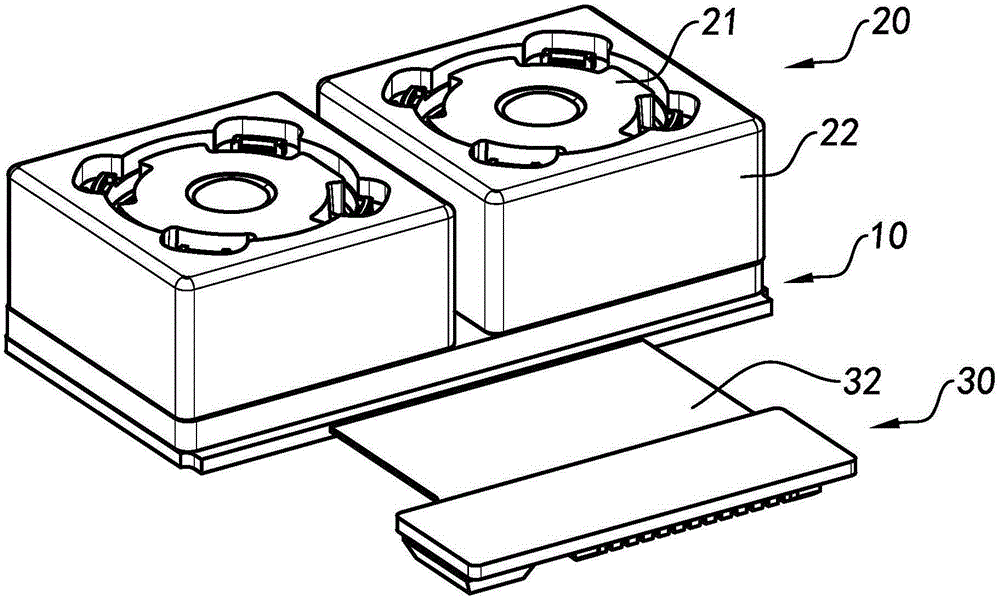
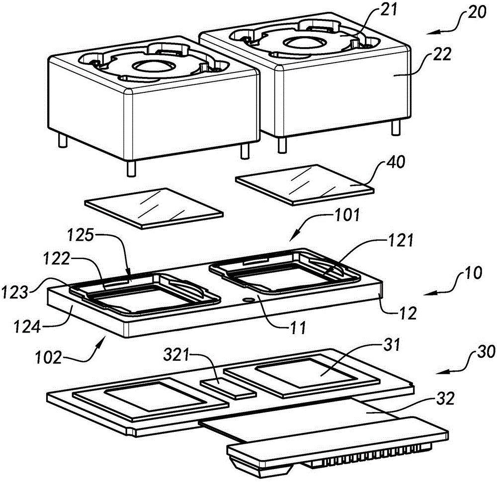
[0061] Such as Figure 2 to Figure 5B Shown is a multi-lens camera module according to a preferred embodiment of the present invention, the multi-lens camera module can be applied to various electronic devices to assist users to take pictures of objects or For images of people, for example, the multi-lens camera module can be used to capture images or videos of objects or people. Preferably, the multi-lens camera module can...


PUM


Abstract

The invention discloses a multi-lens camera module one-piece bracket, a multi-lens camera module and an application of the multi-lens camera module. The multi-lens camera module comprises at least two lens assemblies, at least two light-sensing assemblies and an integrally-molded multi-lens camera module one-piece bracket, wherein the multi-lens camera module one-piece bracket is provided with an upper side part and a lower side part; each lens assembly is connected to the upper side part of the multi-lens camera module one-piece bracket; each light-sensing assembly is connected to the lower side part of the multi-lens camera module one-piece bracket; and the lens assemblies are positioned on light sensing paths of the light-sensing assemblies. Through adoption of the multi-lens camera module one-piece bracket and the multi-lens camera module, the technical defect of deviations in positions, angles and the like among brackets during connection of every independent bracket in the prior art can be overcome, so that the imaging quality of the multi-lens camera module is ensured.

Description

technical field [0001] The invention relates to a multi-lens optical imaging device, in particular to a multi-lens camera module connected bracket, a multi-lens camera module and applications thereof. Background technique [0002] At present, most electronic products are increasingly integrating more functions. This trend makes cross-border products emerge in endlessly. A mobile electronic device with integrated and three-dimensional functions. [0003] In recent years, with the emergence and popularization of WeChat and other social software applied to mobile electronic devices, a new way of communication between people has begun to appear. For example, WeChat launched the function of circle of friends, which allows users to The photos, videos and other images taken by the camera module configured in the mobile electronic device are released for friends to comment or like the content posted by the user. This behavior has changed the relationship between people to a large e...

Claims


Application Information

Patent Timeline
Patent Type & Authority Applications(China)
IPC IPC(8): H04N5/225G03B17/02G03B17/12G03B30/00
CPCG03B30/00H04N23/54H04N23/45H04N23/57G03B11/00G03B17/12H04N23/55
Inventor 张扣文熊科强赵波杰王明珠
Owner NINGBO SUNNY OPOTECH CO LTD
Learn More