
Live suspension clamp fastening device

A technology of suspension wires and clamps, applied in the direction of overhead lines/cable equipment, etc., can solve problems such as looseness, nut 6 falling off and missing, hidden safety hazards, etc., and achieve the effect of reasonable structure and convenient and quick operation

Inactive Publication Date: 2017-11-07
STATE GRID SHANDONG RONGCHENG POWER SUPPLY +1
View PDF7 Cites 0 Cited by
  • Summary
  • Abstract
  • Description
  • Claims
  • Application Information

AI Technical Summary

Problems solved by technology

During the inspection of the line, it was found that because the suspension clamp 2 is in a suspended state, with the shaking of the wire 1, the nut 6 and the bolt 5 often become loose. In severe cases, the nut 6 directly falls off and is lost. The clip 2 and the splint 4 are equipped with high-voltage electricity. When the nut 6 is installed or tightened, the power supply of the entire line needs to be cut off, which will cause a large economic loss. If there is no special tool for live operation Bring greater security risks to maintenance personnel

Method used


Image

  • Live suspension clamp fastening device
  • Live suspension clamp fastening device
  • Live suspension clamp fastening device

Examples


Embodiment 1

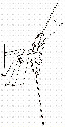
[0017] as attached figure 1 As shown, when the nut 6 needs to be reinstalled after being loose or lost, it is first necessary to clamp the connecting splint 4 on both sides of the suspension clamp 2, and then fix the bolt 5 so that the nut 6 can be firmly tightened on the bolt 5 Above, for this operation step, the following fastening device is provided in this embodiment.

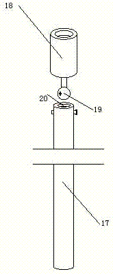
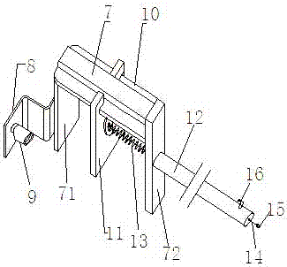
[0018] The fastening device provided in this embodiment includes an attached figure 2 Nutrunner shown with attached image 3 The holder is shown in two parts.

[0019] as attached image 3 As shown, the clamper provided in this embodiment includes an inverted U-shaped clamping frame 7, and an L-shaped bolt positioning plate 8 extending outward is arranged on the front end frame plate 71 of the clamping frame. A bolt sleeve 9 is provided.

[0020] as attached image 3 As shown, slideways 10 are respectively provided on the left and right sides of the back of the clamping frame, and a movable push plat...

Embodiment 2

[0028] The structure of the nut tightener provided in this embodiment is the same as that in Embodiment 1, and only the structure of the holder is further improved.

[0029] Since the clamping force of the movable push plate 11 and the front end frame plate 71 of the clamping frame to the connecting splint 4 on both sides of the suspension clamp 2 in Embodiment 1 only relies on the elastic force of the support spring 13 to clamp, the elastic force is limited, and sometimes it is difficult to fix the suspension. The connecting splints 4 on both sides of the wire clip 2 are clamped and closed, which leads to the need to rely on the tightening force of the nuts to clamp the connecting splints 4 when installing the nuts, making it difficult to install the nuts. In order to solve this problem, this embodiment further improves the holder.

[0030] as attached Figure 4 As shown, the structure of the clamping frame in the clamp provided in this embodiment is consistent with the stru...


PUM


Abstract

The invention belongs to electric power construction or maintenance devices. In order to solve the fastening problem of live suspension wire clamps, the fastening device provided by the present invention includes two parts: a clamper and a nut tightener, and it is characterized in that: the clamper includes an inverted U-shaped clamping frame, An L-shaped bolt positioning plate extending outward is arranged on the front end shelf plate of the clamping frame, and a bolt sleeve is arranged on the bolt positioning plate; slideways are respectively provided on the left and right sides of the back of the clamping frame, and the sides of the clamping frame There is a movable push plate inside, and the top of the movable push plate is provided with a clamping groove matched with the slideway. The slideway is located in the clamping groove. The movable pushplate can move forward and backward along the slideway through the pushing device. The first insulating rod is fixed; the nut tightener includes a second insulating rod, and the top end of the second insulating rod is provided with a nut sleeve. The fastening device has reasonable structure, convenient and fast operation, and ensures good maintenance of the line.

Description

technical field [0001] The invention belongs to electric power construction or maintenance devices, in particular to a live suspension wire clamp fastening device. Background technique [0002] At present, in the process of power transmission, a kind of suspension clamp is often encountered on the power transmission line, and its structure is as attached figure 1 As shown, the wire 1 is clamped by the suspension wire clamp 2, the suspension wire clamp 2 and the fixed block 3 are connected and fixed by the splint 4, one end of the splint 4 is hinged with the suspension wire clamp 2, and the other end of the splint 4 is connected to the fixed block 3 are fixed by bolts 5 and nuts 6. During the inspection of the line, it was found that because the suspension clamp 2 is in a suspended state, with the shaking of the wire 1, the nut 6 and the bolt 5 often become loose. In severe cases, the nut 6 directly falls off and is lost. The clip 2 and the splint 4 are equipped with high-v...

Claims


Application Information

Patent Timeline
Patent Type & Authority Patents(China)
IPC IPC(8): H02G1/02
Inventor 许春华孙维杰张文杰郑媛媛鞠飞钱华建王华阳
Owner STATE GRID SHANDONG RONGCHENG POWER SUPPLY
Learn More