A composite four-axis locking screw locking device and its control method

A lock and screw technology, applied in metal processing equipment, manufacturing tools, metal processing, etc., can solve the problems of inflexible lock, low efficiency and production capacity, and achieve the effect of improving the efficiency of screw lock

Active Publication Date: 2017-09-05
SHENZHEN MIGHT TECH
View PDF4 Cites 0 Cited by
  • Summary
  • Abstract
  • Description
  • Claims
  • Application Information

AI Technical Summary

Problems solved by technology

[0003] In order to overcome the technical defects of the above-mentioned screw locking equipment such as inflexible locking and low efficiency and production capacity, the present invention provides a composite four-axis screw locking equipment with flexible and efficient locking

Method used


Image

  • A composite four-axis locking screw locking device and its control method
  • A composite four-axis locking screw locking device and its control method
  • A composite four-axis locking screw locking device and its control method

Examples


Embodiment 1

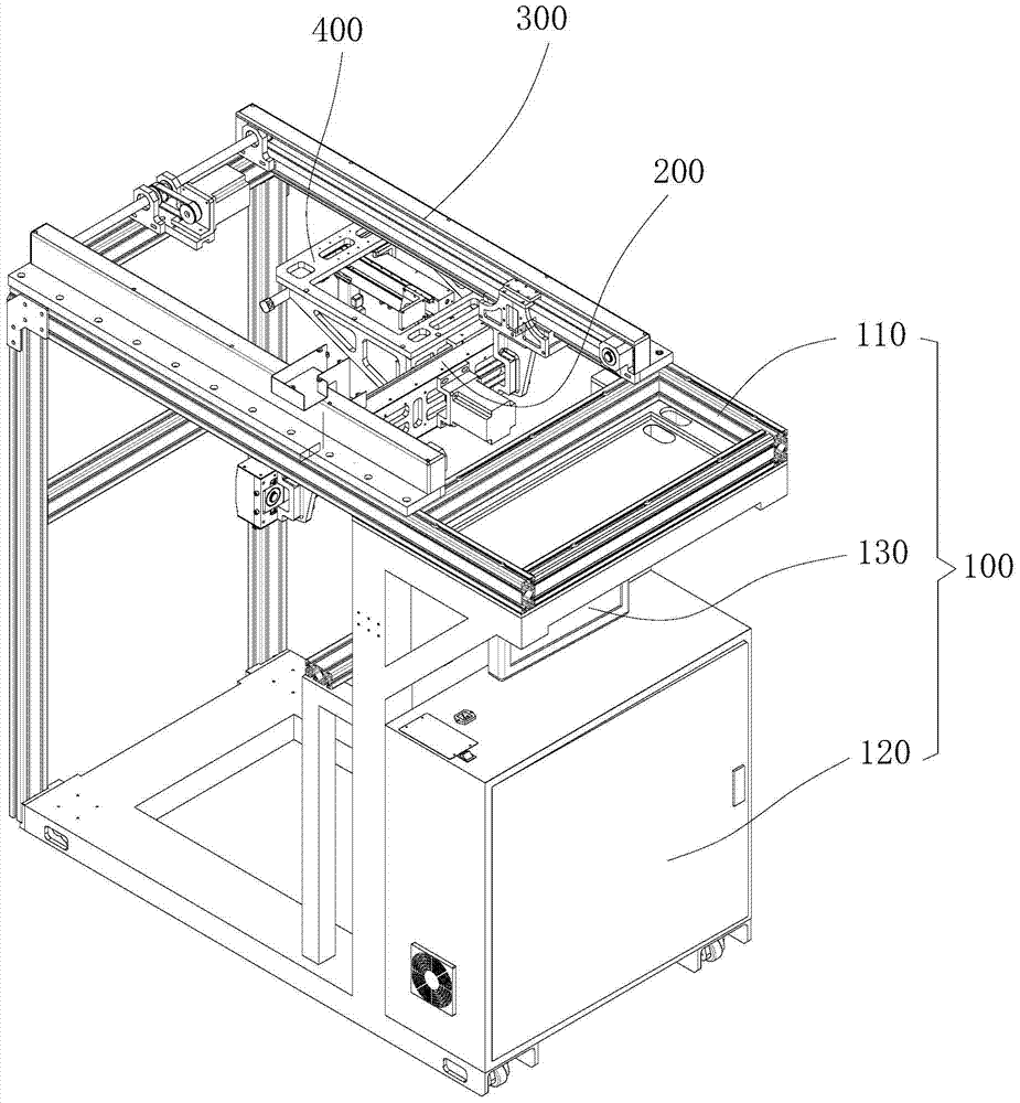
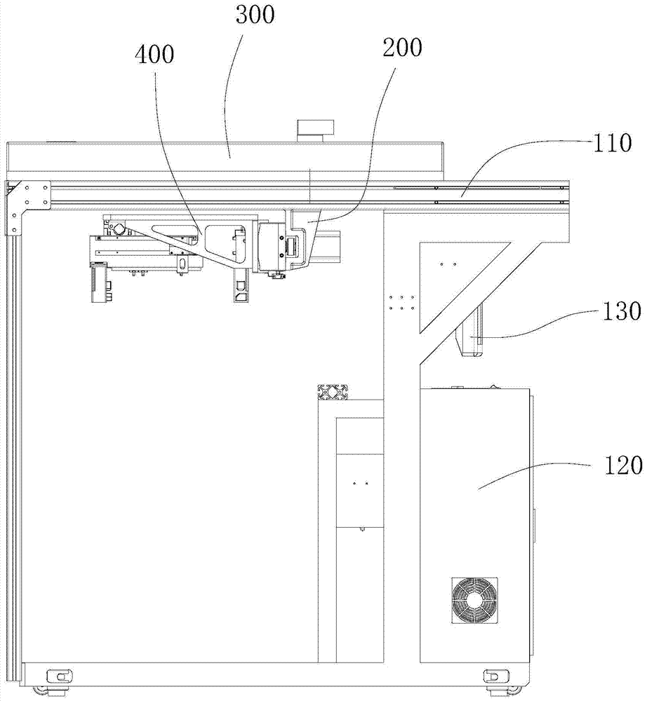
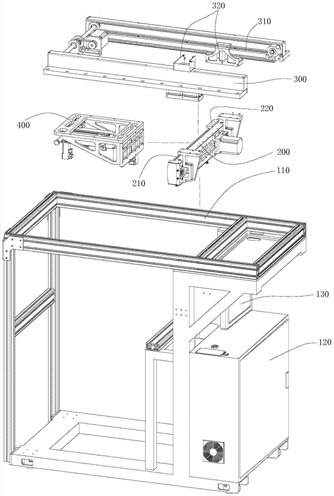
[0032] This embodiment provides a compound four-axis locking screw locking device, such as figure 1 , 2 , 3, including machine installation platform 100, X-axis device, Y-axis device 300, XY coordinate device 400, first electric screwdriver lock 510 and second electric screwdriver lock 520.

[0033] The machine installation platform 100 includes an electric control box 120 , a human-computer interaction interface 130 and an installation frame 110 . The electric control box 120 is used to provide power supply and control processing end for the X-axis device, the Y-axis device 300 and the XY coordinate device 400; Input and output operation and display platform.

[0034] The Y-axis device 300 is arranged on the top of the installation frame 110 of the machine installation platform 100 , and the Y-axis device 300 is provided with a Y-axis guide rail 310 and a Y-axis slider 320 that can move along the Y-axis guide rail 310 along the horizontal and vertical directions.

[0035] ...

Embodiment 2

[0047] This embodiment provides a control method for the composite four-axis locking screw locking device described in the above embodiments, the steps of which are as follows:

[0048] Step 1: Move the product to be locked into the composite four-axis locking screw locking device, and the specific position to be locked is the first coordinate, the second coordinate...;

[0049] Step 2: the first electric screwdriver 512 and the second electric screwdriver suck the screws respectively;

[0050] The third step: the XY coordinate device 400 walks the X coordinate on the X-axis device, and walks the Y coordinate on the Y-axis device 300 under the drive of the X-axis device. The first electric screwdriver 512 walks the X1 coordinate on the XY coordinate device 400, and the second The electric screwdriver moves the Y1 coordinate on the XY coordinate device 400, locates the first electric screwdriver 512 at the first coordinate, and positions the second electric screwdriver at the s...


PUM


Abstract

The invention discloses compound four-axis-lock screw locking equipment. The equipment is characterized by comprising a machine installation platform, an X axis device, a Y axis device, an XY coordinate device, a first electric screw driver locking member and a second electric screw driver locking member. The Y axis device is arranged at the top of the machine installation platform. The X axis device is arranged on the Y axis device. The XY coordinate device is arranged on the X axis device. An XY coordinate system is composed of the Y axis device and the X axis device. The X axis device can slide along the Y axis of the XY coordinate system, and the XY coordinate device can slide along the X axis of the XY coordinate system. The XY coordinate device is provided with a compound X1Y1 coordinate system. The first electric screw driver locking member is arranged on the XY coordinate device and can slide along the X1 axis of the compound X1Y1 coordinate system. The second electric screw driver locking member is arranged on the XY coordinate device and can slide along the Y1 axis of the compound X1Y1 coordinate system. The compound four-axis-lock screw locking equipment is flexible and efficient in locking, and capable of effectively completing locking of various screws distributed irregularly.

Description

technical field [0001] The invention relates to a mechanically processed screw lock collar. In particular, it relates to a composite four-axis locking screw locking device and a control method thereof. Background technique [0002] At present, various large-scale digital products, such as TVs, computers and other products have a large number of screws and are arranged irregularly. It is unrealistic to use manual operations to complete a large number of screw locks. Most of the existing automatic screw locking mechanisms use a single head to operate, and the locking efficiency is still low; for the automatic screw locking mechanism with double heads, the distance between the two heads is fixed, and the product has many screw holes. The distance is flexible and changeable, so that the automatic screw locking mechanism of the double machine head still cannot really realize the simultaneous locking and locking of different screws of the same product by the double machine heads....

Claims


Application Information

Patent Timeline
Patent Type & Authority Patents(China)
IPC IPC(8): B23P19/06
CPCB23P19/06
Inventor 王大利
Owner SHENZHEN MIGHT TECH
Why Eureka
Try Eureka