A Dynamic Modeling Method for Conveying Mechanism of Hybrid Automobile Electrophoretic Coating
A technology of dynamic modeling and conveying mechanism, applied in simulators, electrical digital data processing, program control, etc., can solve problems such as the same or similar methods that have not been seen, and achieve easy programmatic realization, neat and concise expression, and formal neat effect
- Summary
- Abstract
- Description
- Claims
- Application Information
AI Technical Summary
Problems solved by technology
Method used
Image
Examples
Embodiment
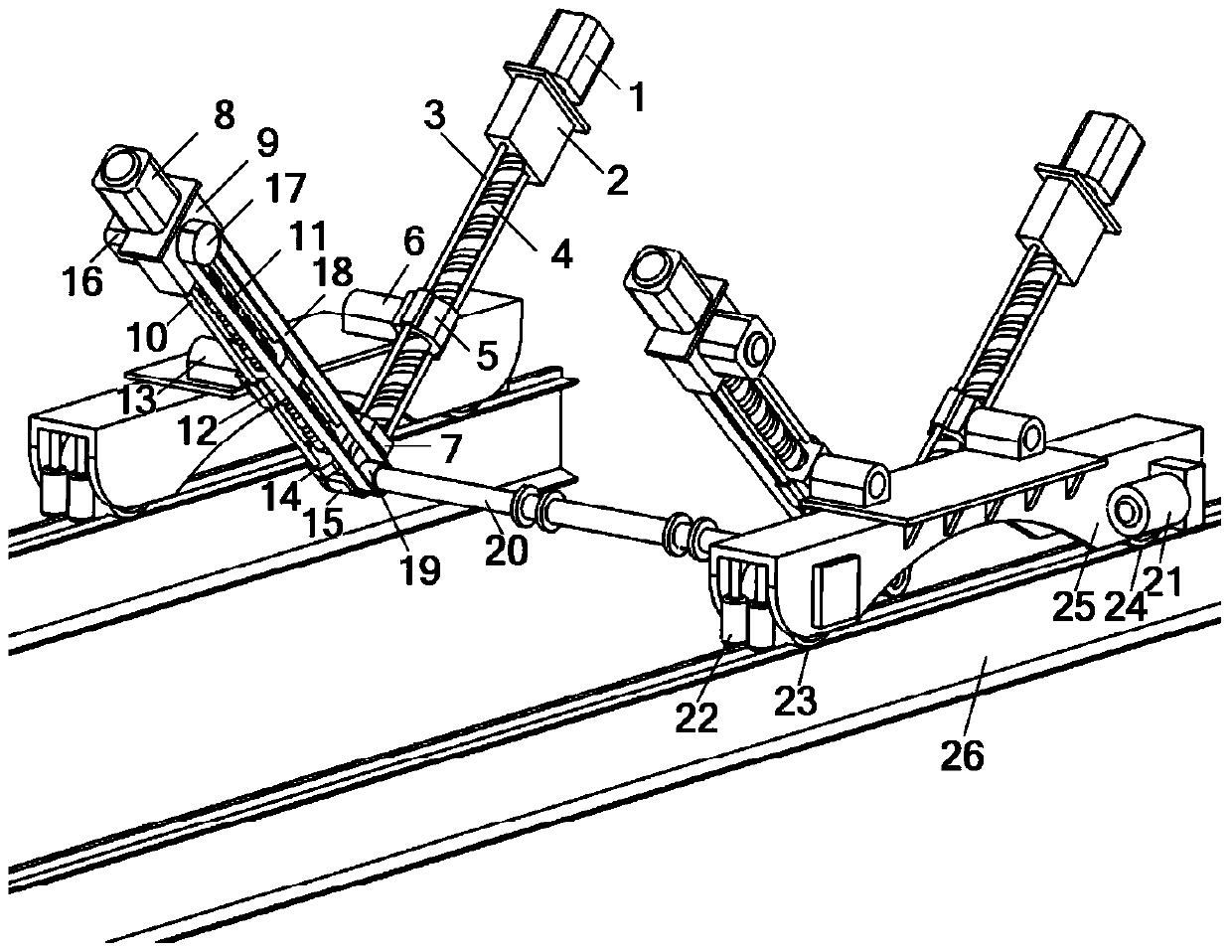
[0066] figure 1 The mechanism is a hybrid automobile electrophoretic coating conveying mechanism, which includes two functional parts: a walking mechanism and a lifting and turning mechanism. Wherein, the walking mechanism realizes the walking transportation function of the conveying mechanism through the cooperation of the walking driver 21, the guide wheel 22, the traveling wheel 23, the traveling wheel 24 and the guide rail 26. The frame of the lifting and turning mechanism is the moving part of the walking mechanism, and the lifting and turning mechanism is mainly composed of two groups of identical plane multi-rod mechanisms. The planar multi-bar mechanism includes three branches, wherein the first branch includes: the first driver 1, the first reducer 2, the first guide rail 3, the first lead screw 4, the first nut 5, the first rotating Auxiliary 6 and first screw seat 7; the first driver 1 is fixed on the first reducer 2, the first guide rail 3, the first screw seat 7 ...
specific Embodiment approach
[0070] The specific implementation of the modeling method of the present invention is as follows:
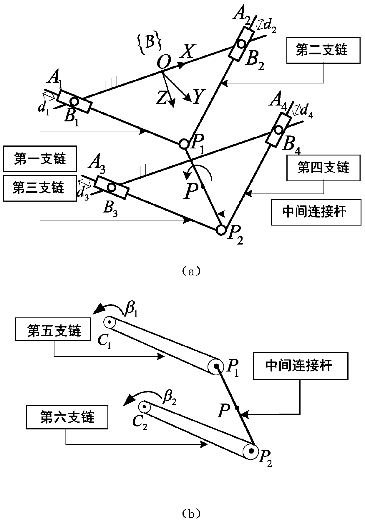
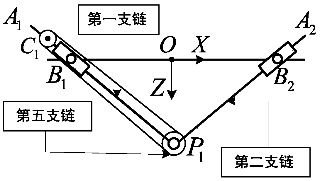
[0071] 1. If figure 2 As shown, the basic coordinate system {B}={O-XYZ} is established, and the origin O is located at B 1 and B 2 The midpoint of , the Z-axis is perpendicular to the base feature plane, and the Y-axis is along the P 1 P 2 Since the parallel mechanism actuation platform only has three degrees of freedom of movement along the X and Y directions and rotation around the Y axis, the pose parameter of the middle connecting rod is selected as q=[x, z, β] T (The units of x and z are m respectively, and the unit of β is rad).
[0072] Depend on figure 2 The analysis shows that the hinge point B between the nut and the base in the first, second, third, and fourth branch chains i (i=1, 2, 3, 4) coordinates in the basic coordinate system and the hinge point P between the two ends of the intermediate connecting rod and each branch chain i The coordinates of (i=1, 2...
PUM
 Abstract
Description
Claims
Application Information
 - R&D
- Intellectual Property
- Life Sciences
- Materials
- Tech Scout
- Unparalleled Data Quality
- Higher Quality Content
- 60% Fewer Hallucinations
Browse by: Latest US Patents, China's latest patents, Technical Efficacy Thesaurus, Application Domain, Technology Topic, Popular Technical Reports.
© 2025 PatSnap. All rights reserved.Legal|Privacy policy|Modern Slavery Act Transparency Statement|Sitemap|About US| Contact US: help@patsnap.com


