
Protector power supply isolation contactless relay

A power isolation, non-contact technology, applied in the direction of emergency protection circuit devices, electrical components, etc., can solve the problems of large volume, difficult layout of circuit boards, and contacts, etc., to achieve the effect of small size

Active Publication Date: 2015-12-09
ZHEJIANG GEYAO ELECTRONICS TECH CO LTD
View PDF5 Cites 2 Cited by
  • Summary
  • Abstract
  • Description
  • Claims
  • Application Information

AI Technical Summary

Problems solved by technology

At present, conventional small DC relays are used in various motor protectors, and the contacts of small DC relays are used to control high-voltage AC contactors. Restrictions, etc. In the 1980s and 1990s, thyristors were used instead of relays in simple motor protectors, because there were devices that could not replace multiple relays to control multiple functions, let alone various protectors and protectors that could not be used for intelligent control. In its equipment, and all strong and weak current circuits have high voltage, there are potential safety hazards. In recent years, similar control methods have rarely been adopted.

Method used


Image

  • Protector power supply isolation contactless relay
  • Protector power supply isolation contactless relay
  • Protector power supply isolation contactless relay

Examples


Embodiment Construction

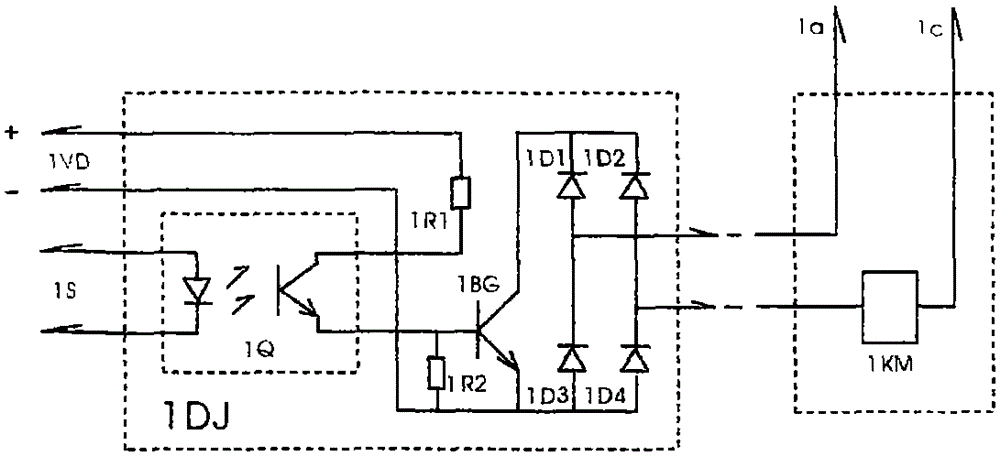
[0020] figure 1 It is the schematic diagram of the protector power supply isolation non-contact relay 1DJ circuit. The working principle of the circuit is that the light-emitting diode of the optocoupler isolator 1Q works when the control signal 1S has the control signal. The isolated power supply 1VD supplies power to the collector of the optocoupler isolator 1Q, and the optocoupler The collector of the isolator 1Q conducts with the emitter of the optocoupler isolator 1Q, the triode 1BG is saturated and conducts, the triode 1BG and the diode 1D1-1D4 bridge rectifier form a non-contact AC switch to conduct, and the AC contactor 1KM pulls in, When the control signal 1S is disconnected, the AC contactor 1KM is shut off to achieve the purpose of control. The specific implementation is that the protector power supply isolation non-contact relay 1DJ uses a high back-voltage triode or composite triode and a bridge rectifier to form a non-contact AC switch circuit, and the base of th...


PUM


Abstract

The invention provides a protector power supply isolation contactless relay. An AC switch is formed by a high counter voltage triode or a composite triode and a bridge rectifier. The base electrode of the high counter voltage triode or the composite triode is controlled by the emission electrode of an optical coupled isolator. Power of the collection electrode of the optical coupled isolator can be supplied by the collection electrode of the triode and can also be supplied by the secondary winding of a switching power supply or an independent isolation power supply. A control signal drives the triode through the optical coupled isolator so that the protector power supply isolation contactless relay is enabled to be conducted to control the contactor of a high-current circuit, and a protector power supply isolation contactless relay circuit and a motor protector can be integrally designed as a whole for planning layout of a circuit board and thus the area and the size of the circuit board can be reduced. The protector power supply isolation contactless relay is contactless, small in size and safe and reliable and can be widely applied to the fields of motor protection devices and electrical automation control.

Description

Technical field: [0001] The invention relates to the fields of pump protectors, motor protectors and intelligent motor protectors, in particular to the protector power isolation non-contact relay. technical background: [0002] The existing solid-state relays are also called non-contact relays or non-contact switches. Due to structural form, volume, price and other reasons, they are only suitable for certain low-voltage electrical appliance control fields, and are not suitable for motor protector control devices. At present, conventional small DC relays are used in various motor protectors, and the contacts of small DC relays are used to control high-voltage AC contactors. Restrictions, etc. In the 1980s and 1990s, thyristors were used instead of relays in simple motor protectors, because there were devices that could not replace multiple relays to control multiple functions, let alone various protectors and protectors that could not be used for intelligent control. Its equ...

Claims


Application Information

Patent Timeline
Patent Type & Authority Applications(China)
IPC IPC(8): H02H7/08
Inventor 介国安吴辉介玠
Owner ZHEJIANG GEYAO ELECTRONICS TECH CO LTD
Learn More