CCD automatic adjusting mechanism

An automatic adjustment and adjustment column technology, applied in nonlinear optics, instruments, optics, etc., can solve the problems of unstable adjustment process, inconvenient manual control, uneven adjustment spacing, etc., to achieve stable adjustment process, easy operation, and fast detection. accurate effect

Inactive Publication Date: 2015-12-09
中山明杰自动化科技有限公司
View PDF5 Cites 3 Cited by
  • Summary
  • Abstract
  • Description
  • Claims
  • Application Information

AI Technical Summary

Problems solved by technology

[0003] In view of the deficiencies in the prior art, the purpose of the present invention is to provide a CCD automatic adjustment mechanism, which solves the problem of uneven adjustment distance by adding a signal receiver and a signal transmitter, and the hydraulic adjustment column solves the problem of unstable adjustment duri

Method used


Image

  • CCD automatic adjusting mechanism

Examples


Embodiment Construction

[0012] In order to make the technical means, creative features, goals and effects achieved by the present invention easy to understand, the present invention will be further described below in conjunction with specific embodiments.

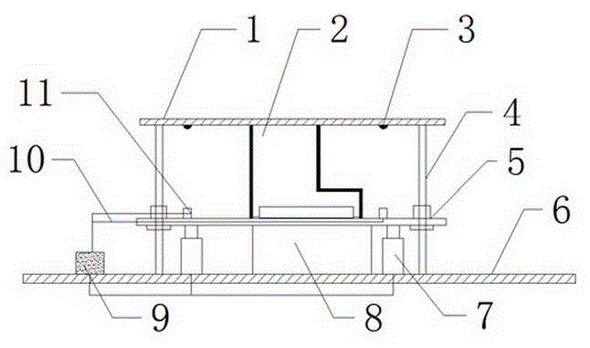
[0013] see figure 1 , the present invention provides a technical solution: a CCD automatic adjustment mechanism, including a main part and a control unit, the main part consists of a connecting plate 1, a CCD2, a main column 4, a floating plate 5, a supporting base plate 6, a hydraulic adjustment column 7 and a protection The cover 8 is composed of a support base plate 6 at the bottom end position. Two main columns 4 are arranged at the symmetrical position in the middle of the support base plate 6. A hydraulic adjustment column 7 is installed on the inner side of the main column 4. The hydraulic adjustment column 7 is composed of two hydraulic adjustment columns. The upper end of the adjustment column 7 is fixed with a floating plate 5. The hydra...


PUM


Abstract

The invention discloses a CCD automatic adjusting mechanism which comprises a main body portion and a control unit. A supporting base plate is positioned on the bottom position, and two main columns are symmetrically arranged on the center of the supporting base plate. A hydraulic adjusting column is installed on the inner side of each main column, a floating plate is fixed on the upper end of each hydraulic adjusting column, and the main columns pass through the floating plate and are connected with the hydraulic adjusting columns. A protective cover is installed on the lower center of the floating plate, and two signal emitters and signal receivers are provided. The signal emitters are respectively installed on the two sides of the bottom of the connection board, the signal receivers are connected with a controller through leads, and the controller is connected with the hydraulic adjusting columns through leads. Compared with the prior art, the CCD automatic adjusting mechanism solves uneven spacing by adding signal receivers and signal emitters. The distance is adjusted automatically, and the hydraulic adjusting columns solve the instability during an adjusting process.

Description

technical field [0001] The invention relates to a CCD automatic adjustment mechanism, which belongs to the field of adjustment mechanism equipment. Background technique [0002] In the prior art, limited by the principles of liquid crystal displays, almost all mainstream liquid crystal displays have a certain "light leakage" problem. Serious "light leakage" problems will affect the quality of the liquid crystal display. Therefore, after the finished product of the liquid crystal display, It is necessary to check whether it leaks light. In the prior art, it is all manual detection. Workers adjust the brightness and contrast of the liquid crystal display to the lowest value. Then, in a dark environment, with a black background, observe the liquid crystal display up and down with naked eyes. Whether there are obvious whitening phenomena on the left and right edges, whether there is light coming through the gaps in the display frame, and finally the workers give corresponding de...

Claims


Application Information

Patent Timeline
IPC IPC(8): G02F1/13
CPCG02F1/1309
Inventor 李振海李遵杰李剑峰吴辉君周建龙梁瑞有周爱明张德
Owner 中山明杰自动化科技有限公司
Why Eureka
Try Eureka