
Push type locking and unlocking mechanism

An unlocking mechanism and push-type technology, applied in the direction of quick-action fasteners, etc., can solve the problems of inability to set up a new locking mechanism, unfavorable operation of unlocking button 1, etc., and achieve short unlocking stroke, high space utilization, and multiple assembly requirements. Effect

Active Publication Date: 2015-12-09
YANFENG ADIENT SEATING CO LTD
View PDF6 Cites 8 Cited by
  • Summary
  • Abstract
  • Description
  • Claims
  • Application Information

AI Technical Summary

Problems solved by technology

[0007] But in the course of practice, the applicant finds that a kind of novel locking mechanism whose publication number is CN103573048A is relatively difficult to replace figure 1 and figure 2 The push-type locking and unlocking mechanism shown is mainly due to the following two aspects. One is to refer to Figure 5 The thickness of a new type of locking mechanism A of CN103573048A shown in CN103573048A generally reaches 30mm, while the thickness of the cover plate 41 at the front end of the cup holder, ashtray and storage box 4 similar to a drawer is only 15mm, so a new type of locking mechanism of CN103573048A cannot be provided A
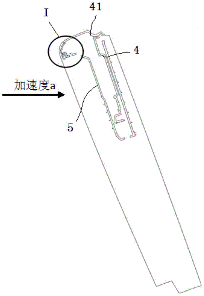
Second, see Image 6 and Figure 7 , the up-and-down movement stroke of the slider A1 of a novel locking mechanism A of CN103573048A should reach 8mm, while the up-and-down stroke of the unlock button 1 in the conventional push-type locking and unlocking mechanism is only 1.6mm, so a kind of CN103573048A The new locking mechanism is not conducive to the operation of the unlock button 1 in the conventional push-type locking and unlocking mechanism

Method used


Image

  • Push type locking and unlocking mechanism
  • Push type locking and unlocking mechanism
  • Push type locking and unlocking mechanism

Examples


Embodiment Construction

[0050] see Figure 8a and Figure 8b , the push-type locking and unlocking mechanism given in the figure includes a housing 100 , a drawer 200 , an unlocking button 300 , a slider 400 , a return torsion spring 500 and two coil springs 600 .

[0051] A drawer chamber 110 is disposed inside the housing 100 , and a drawer opening 120 is disposed on one side of the drawer chamber 110 . The drawer mouth 120 is surrounded by upper eaves 130, front eaves 140, left eaves 150, right eaves 160 and bottom eaves 170, wherein the inner edge of the upper eaves 130 is adjacent to the upper edge of the front eaves 140, and the front The lower edge of the cornice 140 is curved and adjacent to the upper cavity wall 111 front edge of the drawer chamber 110, the upper edge of the left cornice 150 and the right cornice 160 are adjacent to the left and right ends of the upper cornice 130, and the left cornice 150. The upper front edge of the right eaves 160 is adjacent to the left and right ends ...


PUM


Abstract

The invention discloses a push type locking and unlocking mechanism. The push type locking and unlocking mechanism comprises a shell, a drawer, an unlocking button and an elastic element, wherein a drawer cavity and a drawer opening are formed in the shell; the drawer is arranged in the drawer cavity in a sliding mode and used for carrying a cup rack, or an ashtray or a storage box; the drawer is provided with a first buckling part; the unlocking button is arranged on the shell and can move vertically; the elastic element is arranged between the shell and the drawer. The push type locking and unlocking mechanism further comprises a sliding block and a reset torsion spring, wherein the sliding block is arranged on the shell in a sliding mode and can move leftwards and rightwards under the driving of the unlocking button; a second buckle moving leftwards and rightwards along the sliding block is arranged on the sliding block; when the sliding block is in a locking position, the second buckle and the first buckle are mutually engaged; when unlocking is needed, the sliding block drives the second buckle to retreat from the first buckle, so that unlocking is achieved; the two ends of the reset torsion spring are hooked on the shell and the sliding block respectively. By means of the push type locking and unlocking mechanism, the problem of self-unlocking of the mechanism caused by severe brake action when an accident occurs is solved. The push type locking and unlocking mechanism further has the advantages of being shorter in unlocking stroke, higher in space utilization rate and the like. More assembly requirements can be met.

Description

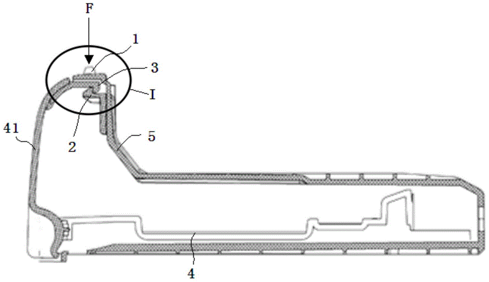
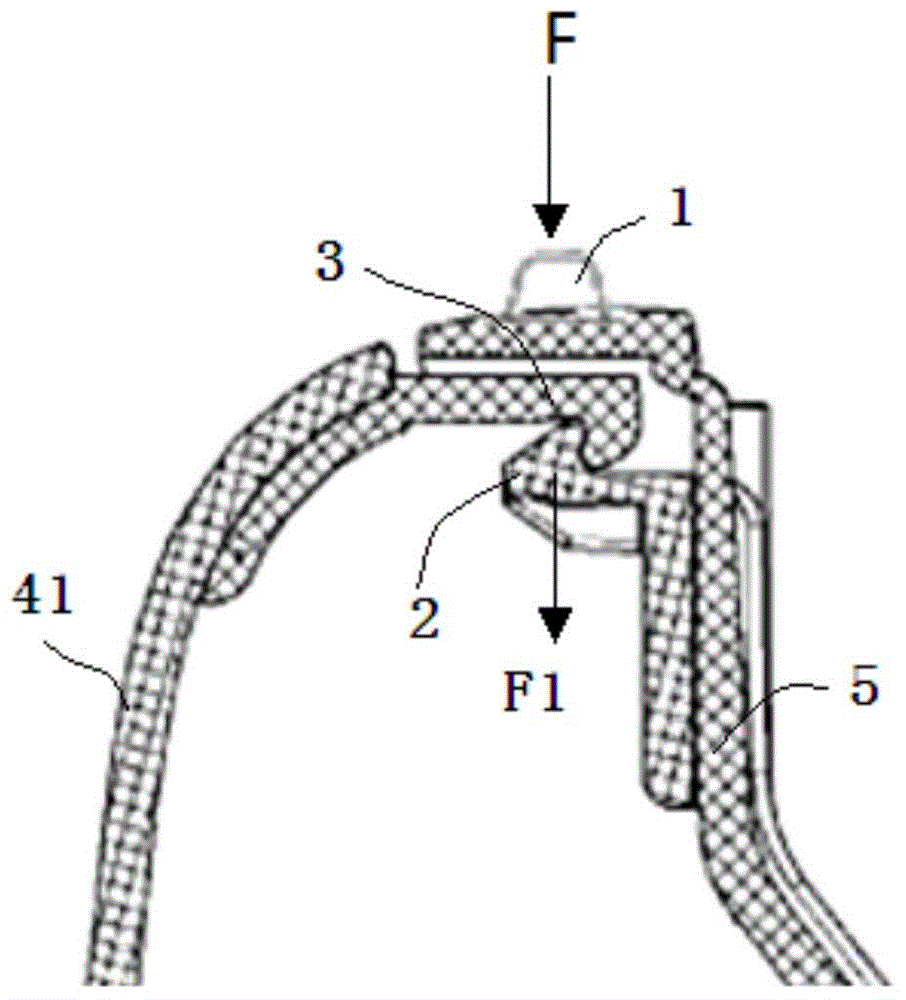
technical field [0001] The present invention relates to a novel locking and unlocking mechanism used in vehicle storage parts. Background technique [0002] Inside the vehicle, there are generally drawer-like cup holders, ashtrays, storage boxes and other compartment accessories with cover plates. Locking and unlocking mechanisms are provided on the cover plates to store drawer-like cup holders, ashtrays, and so on. to close and open interior accessories such as cylinders and storage boxes. [0003] At present, the more commonly used locking and unlocking structure is the push-type locking and unlocking mechanism. see figure 1 and 2 , the existing push-type locking and unlocking mechanism includes an unlocking button 1, a latch 2 and a lock hook 3, and the unlocking button 1 is movably installed on a box body 5 for accommodating cup holders, ashtrays and storage boxes 4 similar to drawers On the front end position of the front end, the latch 2 is fixed on the box body 5,...

Claims


Application Information

Patent Timeline
Patent Type & Authority Applications(China)
IPC IPC(8): F16B21/06
Inventor 沈丽婷欧阳砚武吴晓青李侠
Owner YANFENG ADIENT SEATING CO LTD
Learn More