
Automobile sunshade mechanism

A technology for automobiles and car bodies, which is applied to vehicle parts, movable outer sheaths, transportation and packaging, etc. It can solve the problems of insufficient area, large space occupied by sunshade fans, and coverage, so as to improve stability and space utilization. high effect

Inactive Publication Date: 2015-12-09
NINGBO ZHONGHE AUTO PATS
View PDF10 Cites 1 Cited by
  • Summary
  • Abstract
  • Description
  • Claims
  • Application Information

AI Technical Summary

Problems solved by technology

When the driver enters the car again, even if the driver turns on the air conditioner as soon as he enters the car, it will take a long time to complete the cooling of the cab; moreover, if the car is exposed to the sun, it will also cause damage to the parts of the car. , affecting the service life of these damaged components
In the prior art, the State Intellectual Property Office published on October 17, 2012, the announcement number is "CN101941371A" automobile sunshade fan, which includes a fixed bracket for fixed connection with the roof, and the fixed bracket is provided with a sunshade fan body, the sunshade fan body includes two arms and the fan surface between the fan arms; A result: if the length of the vehicle is 5m, the length of the fan arm must be at least 2.5m to form a covering fan to cover the front and rear of the car, but such a fan will form redundant areas on the left and right sides of the car, and this The extra fan-shaped area on both sides will occupy the parking space required by the cars on the adjacent parking spaces; especially when the heights of the adjacent two cars are inconsistent, such a car sunshade is equivalent to occupying the space of two parking spaces; and, in the front of the car There must be a certain area on both sides and the rear of the car that cannot be covered by the fan
Finally, as mentioned above, the sunshade fan in the prior art takes up a lot of space, but the coverage area of ​​the car body is small.

Method used


Image

  • Automobile sunshade mechanism
  • Automobile sunshade mechanism
  • Automobile sunshade mechanism

Examples


Embodiment Construction

[0030] The present invention will be further described below in conjunction with the drawings and specific embodiments.

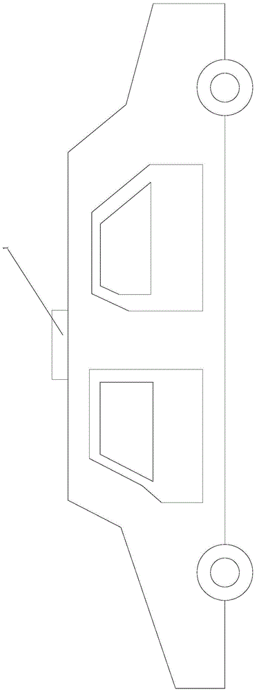
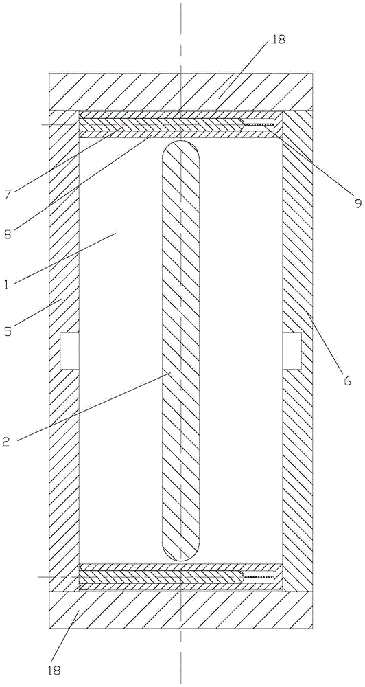
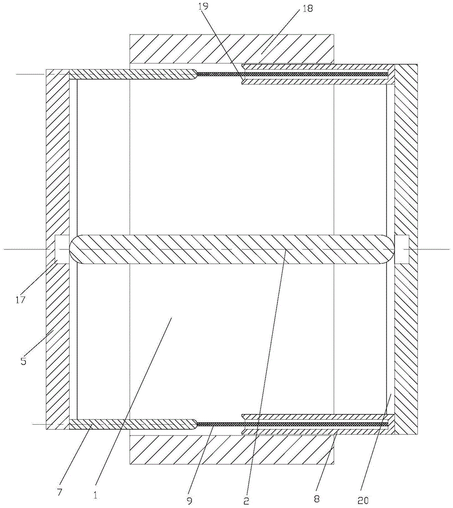
[0031] The working principle of the present invention: when the vehicle is running, the sunshade device is retracted in the base 1, such as figure 1 As shown, the pendulum rod 2 is located between the first push rod 5 and the second push rod 6, and the free end of the guide sleeve 8 on the second push rod 6 is pressed against the side wall of the first push rod 5, that is, the first push rod 5. The second push rod 6 and the two guide sleeves 8 form a quadrilateral structure and shrink inside the base 1. This compact structure can avoid the shaking of the first push rod 5 and the second push rod 6 during the driving of the vehicle noise;

[0032] When the vehicle is parked in the parking space and the sunshade device needs to be opened, the first motor 4 drives the first gear 3 to rotate to drive the swing lever 2 to rotate, such as image 3 As shown; until the p...


PUM


Abstract

The invention discloses an automobile sunshade mechanism which comprises a base (1). A swing rod (2) is rotationally connected to the base (1). On the base (1), a first push rod (5) and a second push rod (6) are arranged on the two sides of the swing rod (2) respectively. Sunshade cloth (25) used for automobile sunshade is connected between the first push rod (5) and the second push rod (6), the two ends of the first push rod (5) are each provided with a guide rod (7), the two ends of the second push rod (6) are each provided with a guide sleeve (8) allowing the corresponding guide rod (7) to slide, and elastic ropes (9) are arranged between the guide rods (7) and the guide sleeves (8). Two sets of ejection devices used for increasing the distance between the first push rod (5) and the second push rod (6) are connected into the swing rod (2) in a sliding mode. The automobile sunshade mechanism is small in occupied space and large in automobile covering area.

Description

Technical field [0001] The invention relates to the technical field of automobile protection, in particular to an automobile sunshade mechanism. Background technique [0002] At present, with the increasing number of cars, private car users' demand for carports is far greater than the supply of public facilities. Especially in the hot summer, the car will inevitably stop in the sun, and the temperature in the car cab will rise sharply. When the driver enters the car again, the driver will turn on the air conditioner as soon as he enters the car, and it will take a long time to complete the cooling of the cab; moreover, the vehicle will be exposed to the hot sun, which will cause damage to the car's parts , Affecting the service life of these damaged parts. In the prior art, the State Intellectual Property Office published on October 17, 2012, the announcement number is "CN101941371A" automobile sunshade fan, which includes a fixed bracket for fixed connection with the car roof,...

Claims


Application Information

Patent Timeline
IPC IPC(8): B60J11/04
Inventor 鲍德夫
Owner NINGBO ZHONGHE AUTO PATS
Learn More