
Intelligent shift overhead shower

A shower and top spray technology, which is applied to spray devices, spray devices, etc., can solve the problems of inability to switch, high cost of use, and inability to meet the needs of shower top spray water style switching.

Active Publication Date: 2018-10-16
ZHEJIANG HUALE TECH CO LTD
View PDF9 Cites 1 Cited by
  • Summary
  • Abstract
  • Description
  • Claims
  • Application Information

AI Technical Summary

Problems solved by technology

[0005] Although the intelligent water-saving shower top spray can achieve intelligent control of the water outlet of the shower top spray through the setting of infrared sensors and solenoid valves, it is limited to the switch of controlling the water flow, which saves water and cannot switch between different water outlet styles. Meet people's needs for switching the spray water style on the shower top
In addition, because of the power consumption structures such as LED lights, infrared sensors, and solenoid valves installed on the top sprayer, it is inevitable to need an external power supply for power supply, which consumes a lot of energy and costs high

Method used


Image

  • Intelligent shift overhead shower
  • Intelligent shift overhead shower
  • Intelligent shift overhead shower

Examples


Embodiment 1

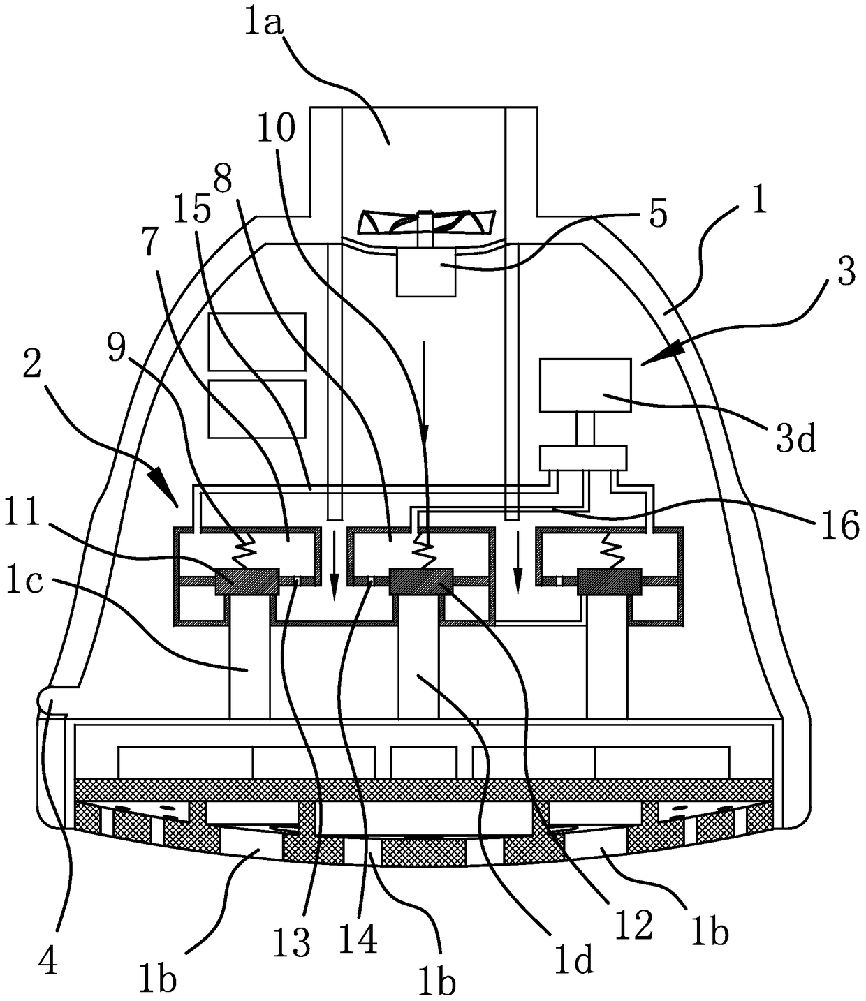
[0036] Such as figure 1 As shown, the intelligent shift top spray shower includes a housing 1 with a water inlet 1a on the upper side. The bottom of the housing 1 is provided with several groups of water outlet holes 1b and the housing 1 has the same number of groups as the water outlet holes 1b. The water outlet cavities are independent of each other, and several water outlet cavities are in one-to-one correspondence with several groups of water outlet holes 1b. The housing 1 is also fixed with a pilot structure 2 with a water inlet and several water outlets 2, a driver 3 capable of driving the pilot structure 2, an inductor 4, and a power supply unit capable of supplying power to the driver 3. Among them, the pilot structure 2 The water inlet is connected to the water inlet 1a of the housing 1, the number of outlets is the same as that of the outlet cavity and the two are in one-to-one correspondence. The driver 3 can drive the pilot structure 2 according to the induction sign...

Embodiment 2

[0045] The structure and working principle of this embodiment are roughly the same as those of the first embodiment, and the difference lies in:

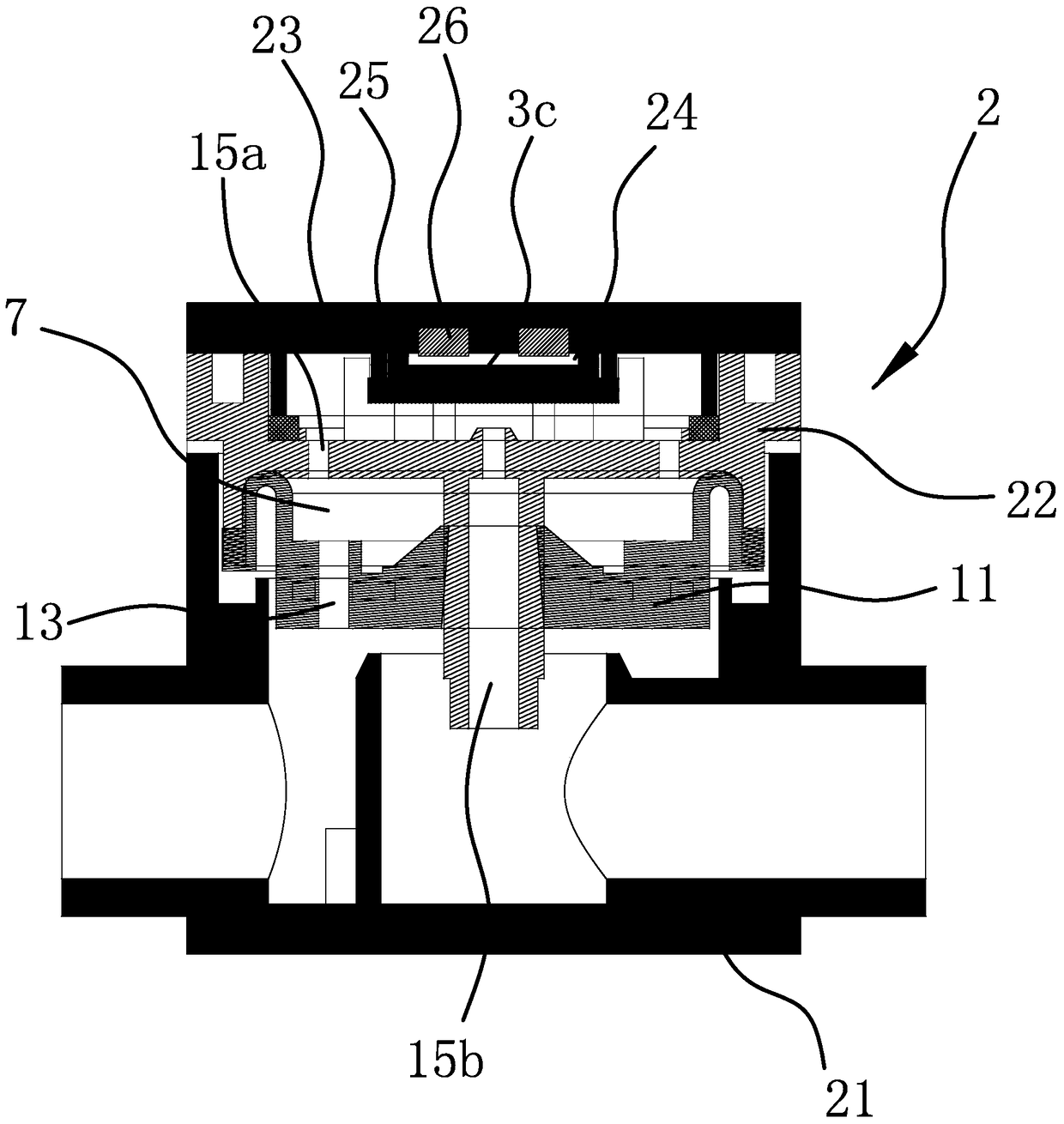
[0046] Such as image 3 As shown, the housing 6 of the pilot structure 2 includes a main body 21 and a middle cover 22 and a top cover 23 that are both arranged on one side of the main body 21. The main body 21 and the middle cover 22 are hermetically connected and a pressure control cavity is formed between the two One 7, the sealing gasket 11 is connected between the middle cover 22 and the main body 21, and a spring 9 (not shown in the figure) is arranged in the pressure control cavity 7. The top cover 23 and the middle cover 22 are hermetically connected and a pressure relief cavity 1 is formed between the two. The pressure relief channel 15 includes a diversion hole 15a and a pressure relief hole 15b both opened on the middle cover 22. Among them, the diversion hole 15a can connect the pressure control cavity 7 and the pressure re...

Embodiment 3

[0052] The structure and working principle of the third embodiment are roughly the same as those of the first embodiment, and the difference lies in:

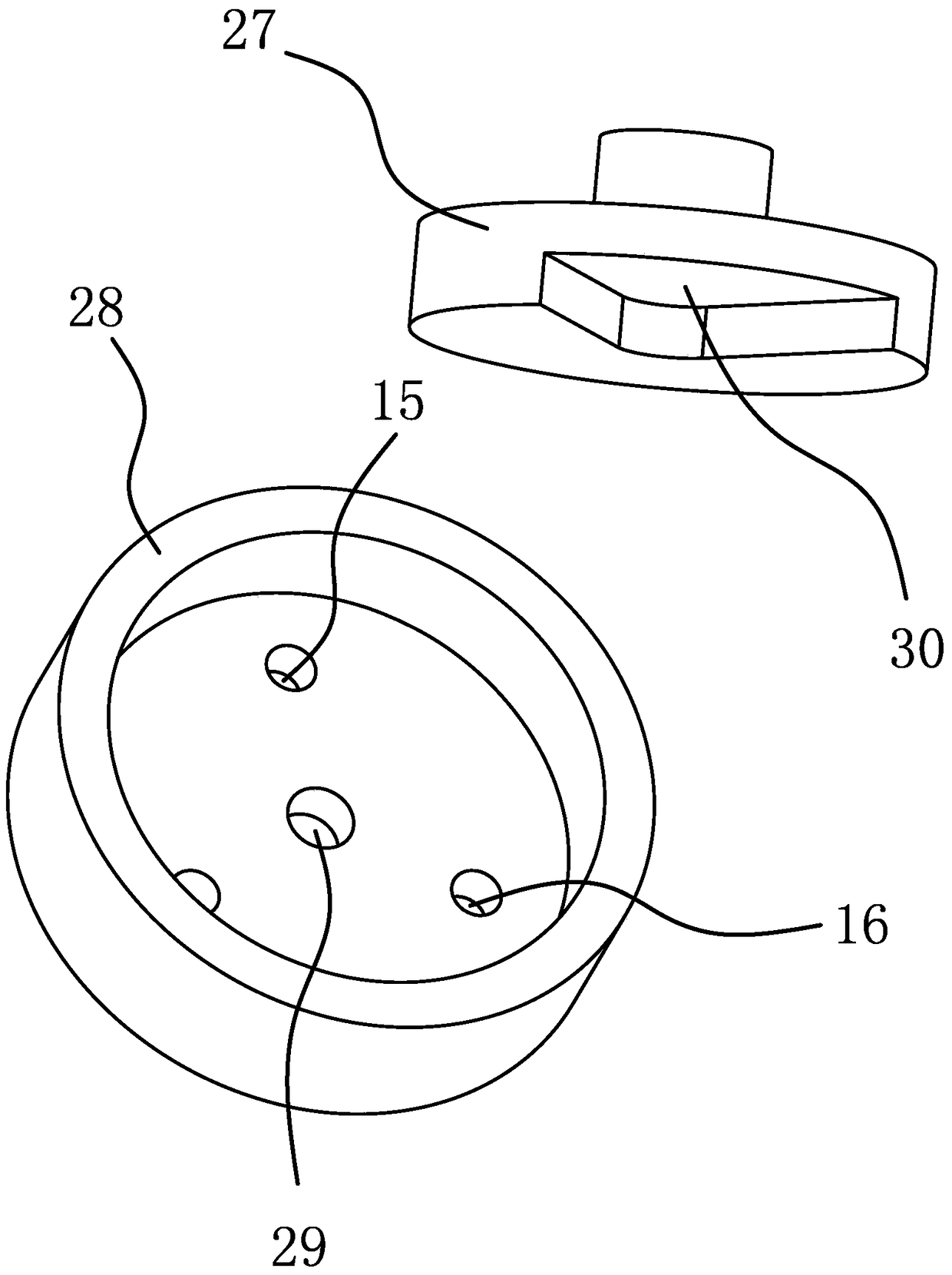
[0053] Such as Figure 4 with Figure 5 As shown, the outer side wall of the housing 6 of the pilot structure 2 has a recessed overflow cavity 17. The pressure relief channel 15 includes a diversion hole 15a and a pressure relief hole 15b. The diversion hole 15a can control the pressure The cavity one 7 is connected to the side of the overflow cavity 17, and the pressure relief hole 15 b connects the water outlet cavity 1 c to the bottom of the overflow cavity 17. The driving member 3 includes an electric component 3a with a blocking portion that is sealed and connected to the opening of the overflow cavity 17. The electric component 3a can drive the blocking portion close to the water inlet port of the pressure relief hole 15b under electric drive and block it. Break the pressure relief hole 15b.

[0054] The pressure control cav...


PUM


Abstract

The invention provides an intelligent gear-shifting top-spray shower head, belongs to the technical field of shower equipment and solves the problems that a conventional top-spray shower head cannot realize automatic gear shifting and is high in cost. The intelligent gear-shifting top-spray shower head comprises a housing with a water inlet formed in the upper side, wherein a plurality of groups of water outlet holes are formed in the bottom of the housing, and mutually independent water outlet cavities of which the number is equal to that of the groups of water outlet holes are formed in the housing; the water outlet cavities are communicated with the groups of water outlet holes in a one-to-one correspondence manner; a leading structure with both a water inlet end and a plurality of water outlet ends, a driving part capable of driving the leading structure, an inductor and a power supply unit capable of powering up the driving part are fixed in the housing; the water inlet end of the leading structure is communicated with the water inlet of the housing, the number of the water outlet ends is equal to that of the water outlet cavities, and the water outlet ends and the water outlet cavities are communicated in a one-to-one correspondence manner; the driving part can drive the leading structure to switch according to an induction signal of the inductor to be optionally communicated with one or more of the water outlet ends. The intelligent gear-shifting top-spray shower head has the advantages of being automatic in control, convenient to use, low in cost and the like.

Description

Technical field [0001] The invention belongs to the technical field of shower equipment, and relates to a top spray shower, in particular to an intelligent shift top spray shower. Background technique [0002] Top spray shower is a kind of shower equipment that is set above the user's head and fixed on the wall, and provides water for the user through the outlet hole at the bottom. Because it does not need to be hand-held, the water outlet angle and the water outlet effect are good. And it is widely used in various families and hotels and other places. The structure of the top spray shower generally includes a housing with a water inlet and a water outlet. The water outlet of the housing is fixedly connected with a water outlet panel. The water outlet panel is evenly distributed with a number of water outlets, and the water is fed from the water inlet of the top spray. , And then sprinkle water out of several water outlet holes on the water outlet panel from the top spray. [000...

Claims


Application Information

Patent Timeline
Patent Type & Authority Patents(China)
IPC IPC(8): B05B1/18B05B1/16B05B12/00
CPCB05B1/1681B05B1/18B05B12/00
Inventor 林泓鑫
Owner ZHEJIANG HUALE TECH CO LTD
Learn More