
Spinning machine frame

A technology of textile racks and pillars, which is applied in the direction of conveying filamentous materials, thin material processing, transportation and packaging, etc., can solve the problems of spinning and spinning of textile bobbins, and the inability to adjust the height of the textile machine, so as to prevent yarn effect of exercise

Inactive Publication Date: 2015-12-02
SUZHOU KANGJIAN TEXTILE
View PDF7 Cites 3 Cited by
  • Summary
  • Abstract
  • Description
  • Claims
  • Application Information

AI Technical Summary

Problems solved by technology

[0002] As we all know, the textile frame is a device used to control the rotation of the spinning bobbin, which is widely used in textile work; the existing textile frame includes a main body, and the top of the main body is provided with a limit rod; when in use, the textile yarn The cooperating work can be carried out by placing the bobbin on the limit rod; however, it is found in its use that because the spinning bobbin will be in contact with the main body, the spinning breakage often occurs during the rotation of the spinning bobbin; height adjustment

Method used

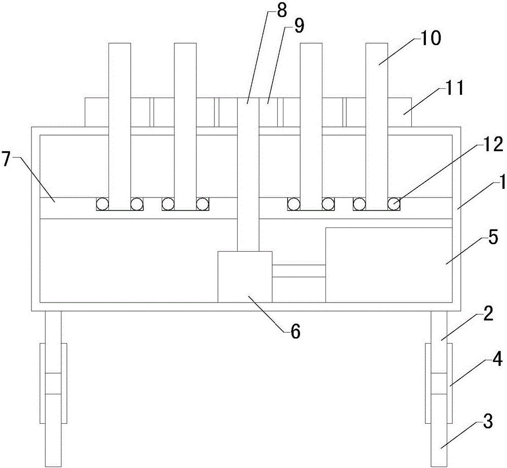

Image

  • Spinning machine frame

Examples


Embodiment Construction

[0009] The specific implementation manners of the present invention will be further described in detail below in conjunction with the accompanying drawings and embodiments. The following examples are used to illustrate the present invention, but are not intended to limit the scope of the present invention.

[0010] Such as figure 1 As shown, the textile frame of the present invention includes a main body 1, an upper pillar 2, a lower pillar 3 and a sleeve 4, the top of the upper pillar is fixed to the bottom of the main body, and the bottom of the upper pillar and the top of the lower pillar are all set There is an external thread structure, and the inside of the casing is provided with an internal thread structure. The bottom end of the upper pillar and the top end of the lower pillar are inserted and screwed inside the casing; the inside of the main body is provided with a working chamber, and a There is a motor 5, a transmission 6 and a shelf 7, the transmission is install...


PUM


Abstract

The invention relates to the technical field of spinning work auxiliary tools, in particular to a spinning machine frame. The height of the spinning machine frame can be adjusted and yarn is prevented from being broken. The spinning machine frame comprises a body and further comprises upper struts, lower struts and casing pipes. A work cavity is formed in the body. A motor, a transmission and a containing rack are arranged in the work cavity. The spinning machine frame further comprises a main rotary shaft, a main gear, multiple auxiliary rotary shafts and multiple auxiliary gears. The main gear is installed at the top end of the main rotary shaft. Multiple containing grooves are formed in the containing rack and each internally provided with a ball bearing. The bottom end of each of the multiple auxiliary rotary shafts penetrates through the body to extend into the work cavity and be inserted in the corresponding ball bearing. Each of the multiple auxiliary gears is installed in the middle of the corresponding auxiliary rotary shaft. The multiple auxiliary rotary shafts are meshed with the main gear together.

Description

technical field [0001] The invention relates to the technical field of textile work auxiliary tools, in particular to a textile frame. Background technique [0002] As we all know, the textile frame is a device used to control the rotation of the spinning bobbin, which is widely used in textile work; the existing textile frame includes a main body, and the top of the main body is provided with a limit rod; when in use, the textile yarn The cooperating work can be carried out by placing the bobbin on the limit rod; however, it is found in its use that because the spinning bobbin will be in contact with the main body, the spinning breakage often occurs during the rotation of the spinning bobbin; height adjustment. Contents of the invention [0003] In order to solve the above-mentioned technical problems, the present invention provides a textile frame that can be adjusted in height and prevents yarn breakage. [0004] The textile frame of the present invention includes a m...

Claims


Application Information

Patent Timeline
IPC IPC(8): B65H54/54
Inventor 王彧韬
Owner SUZHOU KANGJIAN TEXTILE
Learn More