


Quick Research
Generate reliable direction feasibility study reports for your R&D in just a few steps.

Technical Q&A
Discover and master advanced knowledge NOW. Basics, ideas, possibilities, all at once.

Find Solutions
As an expert in R&D theories, this can generate solutions to your technical problems instantly.

Evaluate Feasibility
Analyze your overall solution with one click, know your potential R&D risks in advance.

Monitor Landscape
Get weekly tech updates, stay abreast of the latest tech innovations and key insights.
Blade, wind driven generator and blade manufacturing method
A blade and blade leading edge technology, applied in the field of wind power generation equipment, can solve problems such as poor aerodynamic performance of blades, and achieve the effect of improving aerodynamic performance of blades and solving the reduction of aerodynamic performance of blades
- Summary
- Abstract
- Description
- Claims
- Application Information
AI Technical Summary
Problems solved by technology
Method used
Image

Examples
Embodiment Construction
[0032] The blade, blade manufacturing method and wind power generator according to the embodiments of the present invention will be described in detail below with reference to the accompanying drawings. In this embodiment, the first shell and the second shell refer to two parts constituting the blade.
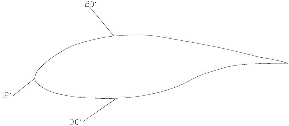
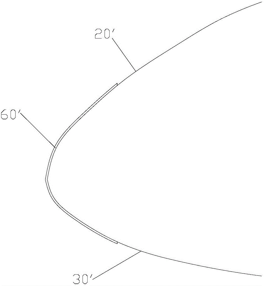
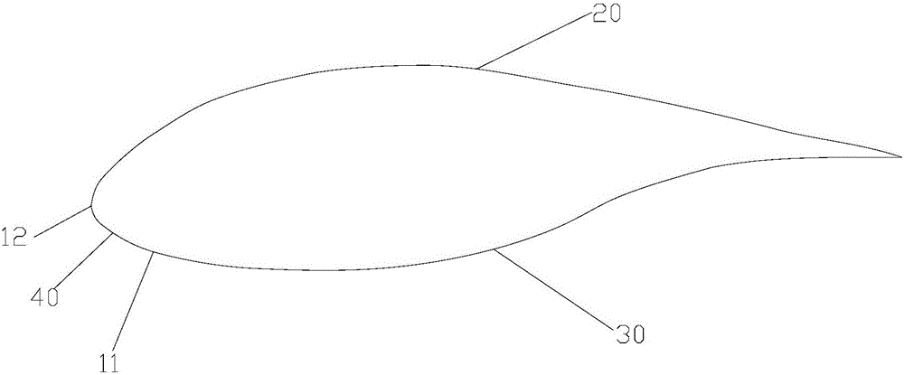
[0033] Such as image 3 As shown, according to the embodiment of the present invention, the blade has a first shell 20 and a second shell 30, and the junction of the first shell 20 and the second shell 30 forms a dividing line 11, along the length direction of the blade, At least a part of the parting line 11 is located on one side of the leading edge 40 of the blade. Since at least a part of the dividing line 11 is located on one side of the blade leading edge 40 (either the suction side or the pressure side), at least a part of the blade leading edge 40 is not divided by the dividing line 11 and is a complete In this way, the problem of unevenness of the leading edge 40 of ...
PUM
 Abstract
Description
Claims
Application Information
 - R&D Engineer
- R&D Manager
- IP Professional
- Industry Leading Data Capabilities
- Powerful AI technology
- Patent DNA Extraction
Browse by: Latest US Patents, China's latest patents, Technical Efficacy Thesaurus, Application Domain, Technology Topic, Popular Technical Reports.
© 2024 PatSnap. All rights reserved.Legal|Privacy policy|Modern Slavery Act Transparency Statement|Sitemap|About US| Contact US: help@patsnap.com