
Wire-stripping machine equipped with three-cutter type stripping mechanism

A technology of wire stripping machine and stripping knife, which is applied in the direction of line/collector parts, equipment for dismantling/armored cables, electrical components, etc. It can solve the problems of affecting the quality of stripping, inconsistent depth, and increasing production costs. The quality of peeling, the effect of solving the centering and balance of peeling

Inactive Publication Date: 2015-11-18
SHENZHEN JALASO AUTOMATION EQUIP CO LTD
View PDF4 Cites 9 Cited by
  • Summary
  • Abstract
  • Description
  • Claims
  • Application Information

AI Technical Summary

Problems solved by technology

[0002] Cables include optical cables, cables, etc. Cables have many uses, mainly used for multiple functions such as controlling installation, connecting equipment, and conveying force. They are common and indispensable objects in daily life. Cables are multi-layered structures. The outside of the cable core is wrapped with multiple layers of protective layers, signal shielding layers, etc. In actual production and life, it is often necessary to peel off the outer layer of the metal core. The layer of cladding is peeled off, and the peeling device adopts a double-cutter head structure, which tightens the cable through the two symmetrically arranged cutter heads, and controls the radial travel of the cutter heads to embed in the outer cladding to peel off the cladding. The defect of this cutter head structure is that the centering of the double cutter head structure is poor, and the axis center deviation is prone to occur when the cable enters the two cutter heads, which leads to inconsistent depths of the two cutter heads embedded in the outer cladding, which affects the peeling quality and is easy to Rework occurs, increasing production costs

Method used


Image

  • Wire-stripping machine equipped with three-cutter type stripping mechanism
  • Wire-stripping machine equipped with three-cutter type stripping mechanism
  • Wire-stripping machine equipped with three-cutter type stripping mechanism

Examples


Embodiment Construction

[0027] The present invention will be further described below in conjunction with accompanying drawing:

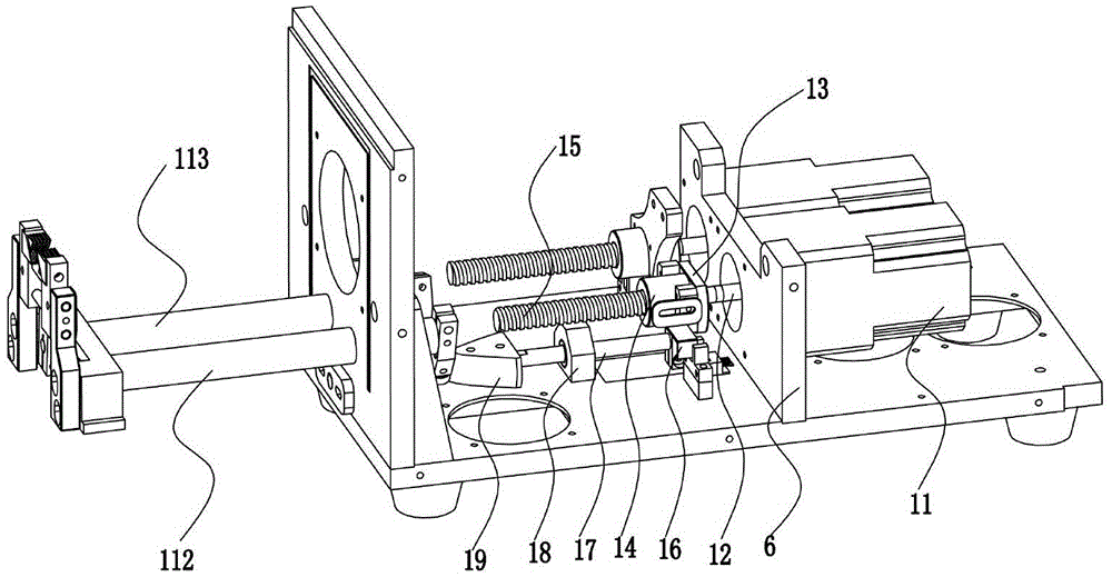
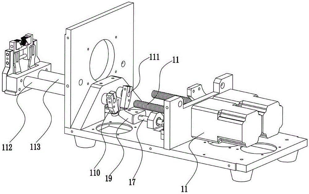
[0028] Such as Figure 1 to Figure 11 As shown, the technical scheme adopted by the present invention is as follows: a wire stripping machine adopting a three-knife stripping knife mechanism, including a knife rest assembly 4, a stripping knife assembly 3, a knife rest driving mechanism 1, a stripping knife rotation driving mechanism 2 and a stripping knife Knife axial movement driving mechanism 5, wherein, the above-mentioned stripping knife assembly 3 extends out of the wire stripping machine, and the inner end of the stripping knife assembly 3 is connected to the stripping knife rotation driving mechanism 2 and the stripping knife axial movement drive 5, so as to drive the stripping knife assembly 3 Radial rotational movement and axial movement; the above-mentioned knife rest assembly 4 protrudes to the outside of the stripping knife assembly 3, and the cable to be strip...


PUM


Abstract

The invention discloses a wire-stripping machine equipped with a three-cutter type stripping mechanism. The wire-stripping machine comprises a cutter rest assembly, a stripping assembly, a cutter rest driving mechanism, a stripping rotation driving mechanism, and a stripping axial motion driving mechanism. The stripping assembly extends out of the wire-stripping machine. The inner end of the stripping assembly is connected with the stripping rotation driving mechanism and the stripping axial motion driving mechanism, so that the stripping assembly is driven to rotate radially and move axially. The cutter rest assembly extends out of the stripping assembly, and a cable to be stripped is placed inside the cutter rest assembly so as to be clamped and fixed. The cutter rest driving mechanism is connected with the inner end of the cutter rest assembly, so the cutter rest assembly is driven to move to enable the cable to be fastened and loosened. The wire-stripping machine is simple in structure. Through adoption of a structure with three cutters that are arranged evenly in a circumferential direction, the high centering effect is exhibited, and the stripping quality is high.

Description

technical field [0001] The invention relates to the field of cables, in particular to a wire stripping machine using a three-knife stripping mechanism. Background technique [0002] Cables include optical cables, cables, etc. Cables have many uses, mainly used for multiple functions such as controlling installation, connecting equipment, and conveying force. They are common and indispensable objects in daily life. Cables are multi-layered structures. The outside of the cable core is wrapped with multiple layers of protective layers, signal shielding layers, etc. In actual production and life, it is often necessary to peel off the outer layer of the metal core. The layer of cladding is peeled off, and the peeling device adopts a double-cutter head structure, which tightens the cable through the two symmetrically arranged cutter heads, and controls the radial travel of the cutter heads to embed in the outer cladding to peel off the cladding. The defect of this cutter head str...

Claims


Application Information

Patent Timeline
IPC IPC(8): H01R43/28H02G1/12
Inventor 蓝石荣
Owner SHENZHEN JALASO AUTOMATION EQUIP CO LTD
Learn More