
Universal system for electronic equipment testability validation and evaluation and testing method

A technology for electronic equipment and general systems, which is applied in the fields of measuring electricity, measuring devices, measuring electrical variables, etc., and can solve the problems of lack of effective technical means to support equipment test verification and evaluation, lack of support equipment, and difficulty in verification of effectiveness.

Active Publication Date: 2015-11-18
NO 63908 TROOPS PLA
View PDF9 Cites 23 Cited by
  • Summary
  • Abstract
  • Description
  • Claims
  • Application Information

AI Technical Summary

Problems solved by technology

[0003] At present, the verification of the effectiveness of the testability design of weaponry is a recognized problem at home and abroad. In the implementation of the testability installation experiment of electronic equipment, there are still the following difficult problems to solve: First, there is a lack of effective technical means to support the testability verification and evaluation of equipment
Equipment testability verification needs to be carried out under the condition of equipment failure, and sufficient failure samples are required. However, for new equipment, due to the lack of failure injection methods, lack of failure samples, and endangering equipment safety and many other factors, many test contents only It can be completed by relying on theoretical calculation or qualitative analysis; secondly, there is a lack of relevant standards and methods to support equipment testability verification and evaluation, and it is difficult to effectively guide equipment testability verification and evaluation work

Method used


Image

  • Universal system for electronic equipment testability validation and evaluation and testing method
  • Universal system for electronic equipment testability validation and evaluation and testing method
  • Universal system for electronic equipment testability validation and evaluation and testing method

Examples


Embodiment Construction

[0024] The technical solutions in the embodiments of the present invention are clearly and completely described below in conjunction with the accompanying drawings in the embodiments of the present invention. Obviously, the described embodiments are only part of the embodiments of the present invention, not all of them. Based on the embodiments of the present invention, all other embodiments obtained by persons of ordinary skill in the art without making creative efforts belong to the protection scope of the present invention.

[0025] In the following description, a lot of specific details are set forth in order to fully understand the present invention, but the present invention can also be implemented in other ways different from those described here, and those skilled in the art can do it without departing from the meaning of the present invention. By analogy, the present invention is therefore not limited to the specific examples disclosed below.

[0026] Such as figure...


PUM


Abstract

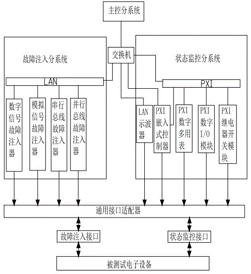
The present invention discloses a universal system for electronic equipment testability validation and evaluation and a testing method, relating to the technical field of the monitoring device or method of electronic equipment. A master control subsystem is used for generating a fault signal and injecting the fault signal into a fault injection subsystem. A state monitoring sub system is used for collecting corresponding fault signal information according to a fault signal monitoring point set by a user, transmitting the information to the master control subsystem in real time and carrying out displaying. The fault injection subsystem is used for generating a corresponding fault signal according to the control command issued by the master control subsystem, coupling and transferring the generated fault signal and inputting the signal to tested electronic equipment through a universal adapter. According to the system, enough failure modes, testing resources and flexible software and hardware configurations are provided, and the various testability validation and evaluation tests of actual electronic equipment can be accurately supported.

Description

technical field [0001] The present invention relates to the technical field of a monitoring device or method for electronic equipment, in particular to a general system and testing method for electronic equipment testability verification and evaluation. Background technique [0002] As a design characteristic of equipment, testability has the same important position as reliability, maintainability and supportability, and is an important part of the general quality characteristics of equipment. Through good testable design, the combat readiness, mission success rate and safety of equipment can be improved, maintenance manpower, equipment and other support resources can be reduced, and life-cycle costs can be reduced. Testable installation verification and evaluation refers to injecting a certain number of faults into the actual equipment or prototype, observing the response of the equipment test system, determining whether the injected faults can be correctly detected and iso...

Claims


Application Information

Patent Timeline
IPC IPC(8): G01R31/00
Inventor 连光耀孙江生张连武闫鹏程冯广斌张西山李会杰王凯蔡丽影梁伟杰周云川吕艳梅魏忠林
Owner NO 63908 TROOPS PLA
Learn More