Ball thrower

A trigger and hemisphere technology, which is applied in the field of ball throwers, can solve the problems of complex structure, poor effect of pet dogs, and not widely used.

Inactive Publication Date: 2015-10-28
黄圭鹏
View PDF5 Cites 1 Cited by
  • Summary
  • Abstract
  • Description
  • Claims
  • Application Information

AI Technical Summary

Problems solved by technology

[0002] At present, the ball thrower that throws the ball for pet dogs has a complex structure, low degree of automation, and poor sensitivity. It is not effective in training pet dogs in practical applications and is not widely used.

Method used


Image

  • Ball thrower

Examples


Embodiment Construction

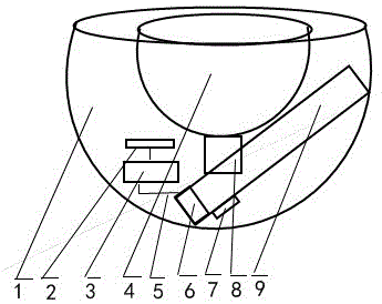
[0006] When the pet dog puts the ball into the semi-circular inner tank, the ball falls from the descending channel, enters the launch tube, touches the trigger, and after the trigger is powered on, the ducted fan starts, ejecting a strong airflow, and throws the ball from the launch tube Because the shell is hemispherical, the distance, angle and direction of the thrown ball may be different each time due to the different throwing forces, which brings more fun to the pet dog. In this way, the task of throwing the ball is completed once Return to the initial state and wait for the pet dog to put it in again.

[0007] The positive effects of the present invention are: the structure is simple, reasonable and novel, the force of serving the ball can be adjusted, and the distance, angle and direction of the thrown ball may be different each time, bringing more fun to the pet dog. It is easy to make, requires less labor, low energy consumption, wide source of materials used, low pr...


PUM


Abstract

The invention provides a ball thrower for a pet dog to play with. The ball thrower is composed of a semispherical housing, an electric regulator, a poleless speed adjusting switch, a ducted blower fan, a trigger, a semispherical inner container, a ball decrease channel and an emission cylinder. The ducted blower fan and the poleless speed adjusting switch are externally operated by personnel for regulating a ball throwing speed. The trigger is connected with the electric regulator, and as long as the trigger is energized, the electric regulator starts the deducted blower fan to eject a powerful air flow to throw a ball out of the emission cylinder.

Description

technical field [0001] The invention belongs to the technical field of throwing balls, in particular to a ball thrower for playing with pet dogs. Background technique [0002] At present, the ball thrower for throwing a ball for pet dogs has complex structure, low degree of automation, and poor sensitivity. In practical application, the effect of training pet dogs is poor, and the application is not widely used. Contents of the invention [0003] The object of the present invention is to provide a ball throwing device for pet dogs, which has a simple, reasonable and novel structure, easy manipulation, low cost, can overcome the defects in the background technology and has its advantages, and has good training effect for pet dogs and strong practicability . [0004] The technical scheme adopted to realize the present invention is: the shell of the ball thrower hemisphere, electric regulator, battery, stepless speed regulation switch, ducted fan, trigger, hemisphere liner, ...

Claims


Application Information

Patent Timeline
IPC IPC(8): A01K15/02
CPCA01K15/025
Inventor 黄圭鹏
Owner 黄圭鹏
Why Eureka
Try Eureka