
an electric clipper

An electric clipper and power supply technology, applied in metal processing and other directions, can solve the problems of unreasonable structure setting, complicated and inconvenient assembly, and high manufacturing cost, and achieve the effects of good blade adjustment effect, quick assembly and low manufacturing cost.

Active Publication Date: 2017-01-18
NINGBO JIAMEI ELECTRIC
View PDF9 Cites 1 Cited by
  • Summary
  • Abstract
  • Description
  • Claims
  • Application Information

AI Technical Summary

Problems solved by technology

However, due to the unreasonable structural setting of the blade adjustment mechanism of the existing electric clippers, the structural setting of the whole machine is more complicated, the assembly is more cumbersome and inconvenient, the processing is more difficult, and the manufacturing cost is higher.

Method used


Image

  • an electric clipper
  • an electric clipper
  • an electric clipper

Examples


Embodiment Construction

[0027] The present invention will be further described below in conjunction with the accompanying drawings.

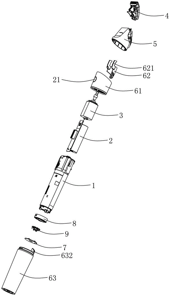
[0028] Such as Figure 1 to Figure 9 The electric clipper shown includes a housing 1, a blade assembly 4 and a blade adjustment mechanism. The housing 1 is respectively provided with a power supply assembly 2 and a motor 3 electrically connected to the power supply assembly 2. The blade assembly 4 includes a mounting plate 41 1. The static blade 42 fixed on the mounting plate 41, the movable blade 43 which is movably located on the mounting plate 41 and driven by the motor 3, the mounting plate 41 is installed on the front end of the housing 1 through the cutter head seat 5, and on the mounting plate 41 Hingedly be provided with the transmission block 44 that matches with movable blade 43, be connected with torsion spring 45 between transmission block 44 and movable blade 43, blade adjustment mechanism comprises adjustment cover 61 and adjustment frame 62, the front en...


PUM


Abstract

The invention discloses an electric hair cutter which comprises a shell, a blade assembly and a blade adjusting mechanism. The blade assembly comprises an installation board, a static blade and a movable blade. A transmission block matched with the movable blade is hinged to the installation board. The blade adjusting mechanism comprises an adjusting sleeve and an adjusting frame. A push rod in transmission fit with the transmission block is arranged at the front end of the adjusting frame. The shell is fixedly sleeved with the adjusting sleeve. The adjusting frame is movably arranged between the adjusting sleeve and the shell. The adjusting frame is in sliding fit with the shell through chutes. A protruding block is arranged at the rear end of the adjusting frame. The blade adjusting mechanism further comprises an outer shell, wherein the shell is movably sleeved with the outer shell. A gear board used for driving the adjusting frame to move along the chutes extends from the front end of the outer shell and is provided with gear teeth in a stepped shape. A first spring is arranged between the adjusting frame and the shell and makes the protruding block matched with the gear teeth in an abutting manner all the time. The electric hair cutter is simple and reasonable in structure, convenient to assemble, easy to machine and low in manufacturing cost.

Description

technical field [0001] The invention relates to the technical field of hairdressing tools, in particular to an electric clipper. Background technique [0002] Electric clippers are a common tool for trimming hair or animal hair, and are well known and common. The structure of the electric clipper mainly includes a housing in which a motor and a power supply assembly are arranged, and a blade assembly driven by the motor is provided at the front end of the housing. For the convenience of use, most of the common electric clippers on the market are equipped with a blade adjustment mechanism, and the blade adjustment mechanism is used to adjust the position of the moving blade, so as to achieve the effect of trimming hairs of different lengths. However, due to the unreasonable structural setting of the blade adjustment mechanism of the existing electric clippers, the structural setting of the whole machine is relatively complicated, the assembly is cumbersome and inconvenient, ...

Claims


Application Information

Patent Timeline
Patent Type & Authority Patents(China)
IPC IPC(8): B26B19/02B26B19/38
Inventor 陈耀其
Owner NINGBO JIAMEI ELECTRIC
Learn More