
Light transmitting and air ventilating structure inside building

A technology for building and ventilation channels, which is applied to building components, building structures, buildings, etc. It can solve the problems of poor air permeability, air flow, and poor lighting in rooms, and achieve comfortable lighting and energy saving effects.

Active Publication Date: 2015-10-07
浙江省工业设计研究院有限公司
View PDF11 Cites 0 Cited by
  • Summary
  • Abstract
  • Description
  • Claims
  • Application Information

AI Technical Summary

Problems solved by technology

With the improvement of living standards and the growth of population, in order to further improve the space utilization rate of buildings, most of the current housing buildings are buildings. In order to maximize the use of space, the width of buildings is getting larger and larger, so that Another problem is that the building is too wide so that the interior of the building is far away from the windows, the interior space is dimly lit, and the ventilation in the room is poor; especially in some over-wide housing buildings or apartment buildings, there are often only single-sided windows, and If people design two rooms in this kind of building, the inner room has poor lighting or no light at all because it is far away from the window, and at the same time it cannot breathe. Living in it will make people feel stuffy
In addition, in winter, traditional houses use heating or air conditioning for heating, which wastes energy; and the interior of the room needs to be sealed, so that the air flow is blocked

Method used


Image

  • Light transmitting and air ventilating structure inside building
  • Light transmitting and air ventilating structure inside building
  • Light transmitting and air ventilating structure inside building

Examples


Embodiment Construction

[0017] Below in conjunction with accompanying drawing and embodiment the present invention is further described:

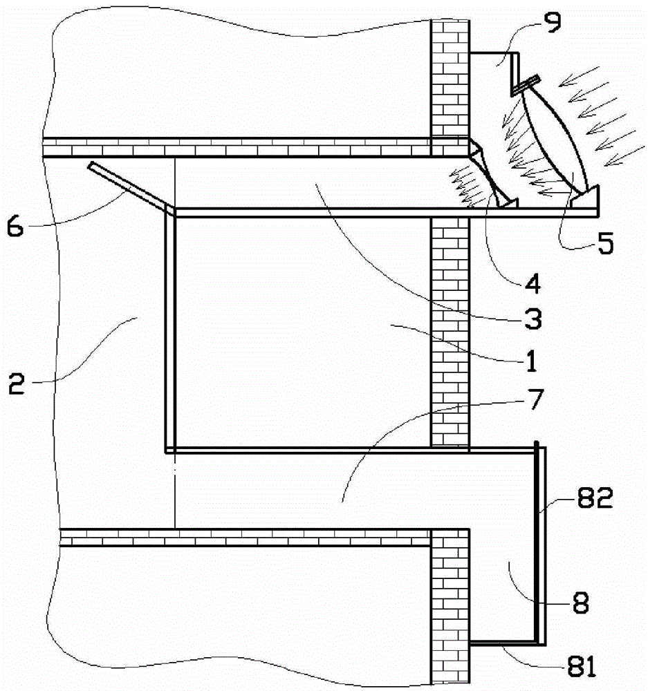
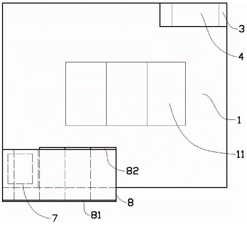
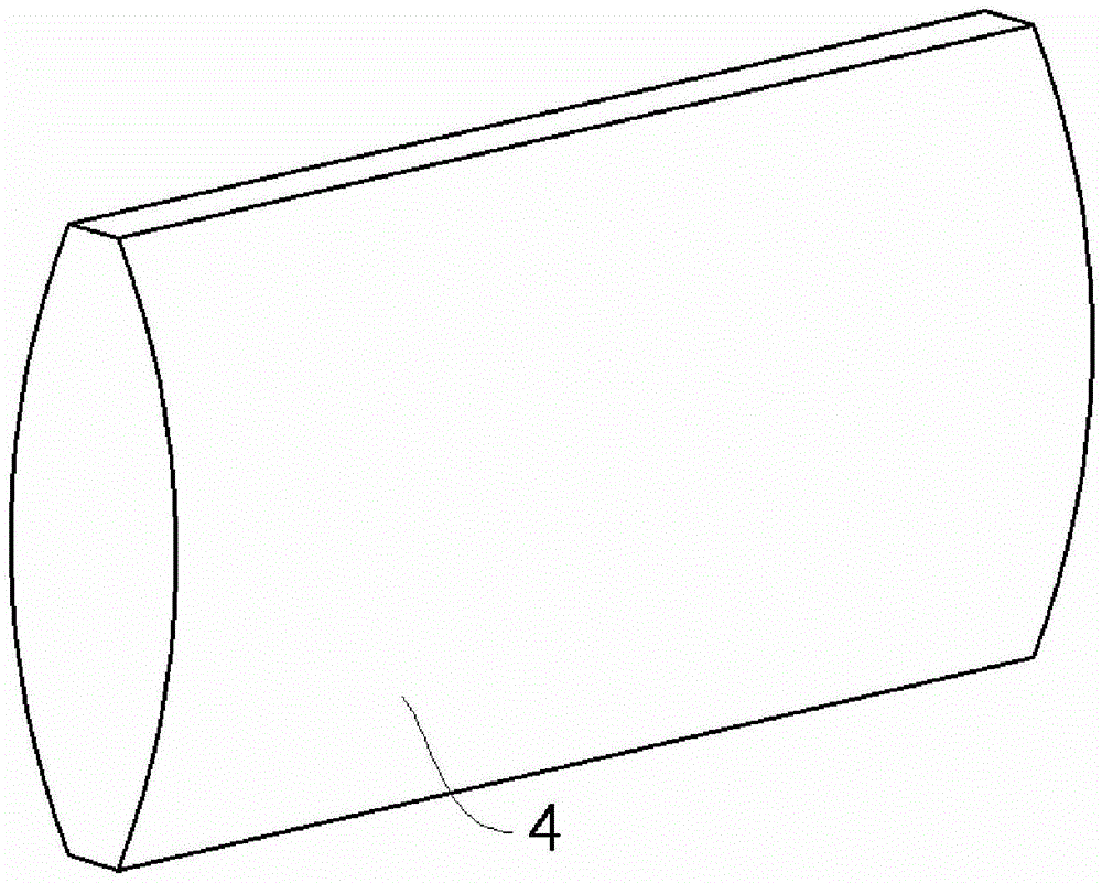
[0018] Such as figure 1 and figure 2 As shown in the embodiment, the light-transmitting and ventilating structure inside the building is used in high-rise buildings with no windows in the interior rooms, including a windowed room 1 and a windowless room 2; the ceiling corner position of the windowed room 1 is designed as follows: The optical path channel 3 connected to the upper part of the windowless room 2, the inner wall of the optical path channel 3 is attached with a reflective mirror, the lower wall of the optical path channel 3 protrudes from the wall of the windowed room 1, and the optical path The outer exit position of the channel 3 is designed with a concave mirror 4 that is transparent and inclined to diverge the light. The concave mirror 4 is obliquely equipped with a convex mirror 5 that is coaxial with the concave mirror and can gather the light. ...


PUM


Abstract

The invention provides a light transmitting and air ventilating structure inside a building. The structure is used in a high-rise building where an internal room has no windows. The structure comprises a windowed room and a windowless room; a ceiling corner position of the windowed room is designed to be provided with a light channel which is communicated with the upper portion of the windowless room, reflective mirrors are attached to the inner walls of the light channel, the lower wall of the light channel extends out of the wall of the windowed room, a transparent and inclined concave mirror used for diverging light is arranged at an external outlet position of the light channel, a convex mirror is assembled above the concave mirror obliquely, and a light output lens is arranged at an outlet position, penetrating into the windowless room, of the light channel. By means of the structure, the effects of light transmitting and air ventilating can be achieved in a building internal room which has no windows originally, a user can feel more comfortable, the lighting is better, it is unnecessary to turn on a lamp at daytime, and energy resources can be saved.

Description

Technical field [0001] The invention belongs to the technical field of building structures, and in particular relates to a light-transmitting and ventilation structure inside a building. Background technique [0002] Architecture is an artificial environment created by people in order to meet the needs of social life, using the material and technological means they have mastered, and using certain scientific laws, feng shui concepts and aesthetic principles. Among all kinds of buildings, the most related to people's life are undoubtedly residential and office buildings. With the improvement of living standards and the growth of population, in order to further improve the space utilization rate of buildings, most of the current housing buildings are buildings. In order to maximize the use of space, the width of buildings is getting larger and larger, so that Another problem is that the building is too wide so that the interior of the building is far away from the windows, th...

Claims


Application Information

Patent Timeline
Patent Type & Authority Applications(China)
IPC IPC(8): E04F17/06E04F17/04
Inventor 陈伟强
Owner 浙江省工业设计研究院有限公司
Learn More