LED drive module applicable to time-sharing multiplexing, drive circuit and working methods

A technology of LED drive and drive module, which is applied in the field of drive circuit and LED drive module, can solve the problems of unoptimized LED drive circuit and complex circuit, and achieve the effect of simple LED drive module, optimized drive circuit, and reduced circuit cost

Inactive Publication Date: 2015-09-30
CHANGZHOU TOPIC SEMICON TECH
View PDF9 Cites 3 Cited by
  • Summary
  • Abstract
  • Description
  • Claims
  • Application Information

AI Technical Summary

Problems solved by technology

[0003] The LED drive module used in the traditional switch-mode regulated power supply, the LED drive module includes CS terminal (current sampling terminal) and ZCD terminal (zero-crossing detection terminal), and the two ports are connected to the corresponding circuit by means of independent settings. This connection method does not realize the optimization of the LED driving circuit, which makes the circuit complicated to some extent

Method used


Image

  • LED drive module applicable to time-sharing multiplexing, drive circuit and working methods
  • LED drive module applicable to time-sharing multiplexing, drive circuit and working methods

Examples


Embodiment 1

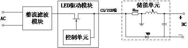
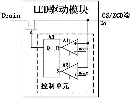
[0022] Such as figure 1 with figure 2 As shown, an LED driver module of the present invention includes: a power switch tube, the power switch tube is controlled by a control unit to be turned on or off, and the control unit is provided with a time-division multiplexing terminal, that is, a CS / ZCD terminal ; When the time-division multiplexing terminal is used as the CS terminal, if the CS level is greater than a set upper limit value Uref1, then turn off the power switch tube, or when used as the ZCD terminal, if the ZCD level is lower than a set lower limit value Uref2, then turn on the power switch tube.

[0023] Further, the control unit includes: a first comparator A1 adapted to access the upper limit value Uref1, a second comparator A2 adapted to access the lower limit value Uref2; The RS flip-flop A3 connected to the output end of the second comparator A2, the output end of the RS flip-flop A3 is connected to the control end of the power switch tube; the other input e...

Embodiment 2

[0030] On the basis of Embodiment 1, the present invention also provides a working method of the LED driving module, the LED driving module is provided with a time-division multiplexing terminal, that is, a CS / ZCD terminal; the working method, that is, when the dividing When the multiplexing terminal is used as the CS terminal, if the CS level is greater than a set upper limit value Uref1, the power switch tube will be turned off, or when used as the ZCD terminal, if the ZCD level is lower than a set lower limit value Uref2, it will be turned on Power switch tube.

Embodiment 3

[0032] In Embodiment 1, the present invention also provides a driving circuit of an LED driving module, including: an energy storage unit, which is sequentially connected by a resistor Rcs, an energy storage inductor, an output capacitor and a freewheeling diode, and constitutes a loop, and the CS / ZCD end is connected to one end of the resistor Rcs to collect the CS level or ZCD level, and the other end of the resistor Rcs is grounded.


PUM


Abstract

The invention relates to an LED drive module applicable to time-sharing multiplexing, a drive circuit and working methods. The LED drive module comprises a power switch tube which is controlled by a control unit to be switched on or off, wherein the control unit is provided with a time-sharing multiplexing end, namely, a CS / ZCD end; when the time-sharing multiplexing end serves as the CS end, the power switch tube is switched off if the CS level is higher than a set upper limit value, or when the time-sharing multiplexing end serves as the ZCD end, the power switch tube is switched on if the ZCD level is lower than a set lower limit value. According to the LED drive module and the working method thereof as well as the drive circuit applying the LED drive module and the working method of the drive circuit, time-sharing control of the power switch tube is realized by the aid of the time-sharing multiplexing end of the LED drive module, the LED drive module is more concise, the drive circuit constituted by the LED drive module is more optimized, and the circuit cost is reduced effectively.

Description

technical field [0001] The invention relates to the field of LED driving power supply, in particular to an LED driving module, a driving circuit and a working method suitable for time-division multiplexing. Background technique [0002] With the development of LED technology, LED lamps are more and more widely used in low-brightness lighting and even in daily life due to their advantages of environmental protection and energy saving, low power consumption, and long service life. LEDs need to work in low-voltage DC state , when the mains power supply is used, it must be rectified into direct current, and then the LED working current and voltage are provided by the switching regulated power supply. [0003] The LED drive module used in the traditional switch-mode regulated power supply, the LED drive module includes CS terminal (current sampling terminal) and ZCD terminal (zero-crossing detection terminal), and the two ports are connected to the corresponding circuit by means ...

Claims


Application Information

Patent Timeline
IPC IPC(8): H05B37/02
CPCY02B20/40
Inventor 张永良
Owner CHANGZHOU TOPIC SEMICON TECH
Why Eureka
Try Eureka