Cyclic type mold-clamping mechanism

A mold clamping mechanism and circulation technology, applied in the field of mold clamping mechanism, can solve the problems of manual operation and human access for mold clamping

Inactive Publication Date: 2015-09-30
ANHUI KINGPOWER EQUIP & MOLD MFR
View PDF5 Cites 1 Cited by
  • Summary
  • Abstract
  • Description
  • Claims
  • Application Information

AI Technical Summary

Problems solved by technology

However, there are still many places in the production process that require human intervention
For example, manual work is required for mold closing after mold injection

Method used


Image

  • Cyclic type mold-clamping mechanism
  • Cyclic type mold-clamping mechanism
  • Cyclic type mold-clamping mechanism

Examples


Embodiment Construction

[0018] The present invention will be described in further detail below in conjunction with the accompanying drawings.

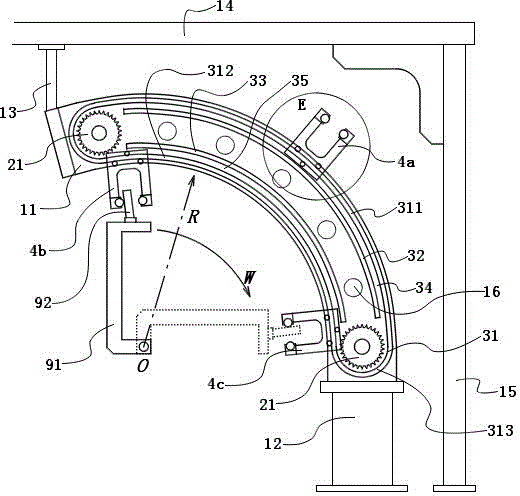
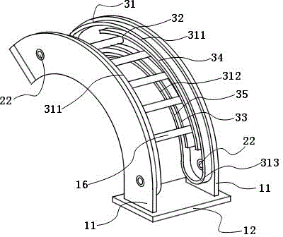
[0019] Such as figure 1 , figure 2 , image 3 , Figure 4 As shown, a circular mold clamping mechanism includes a chain, a frame and a mold clamping gripper. The frame is made up of two side plates 11 and a supporting mechanism. The supporting mechanism includes a base 12 , a top bracket 13 , a top beam 14 , and a column 15 . The side plate 11 is an arc-shaped plate body. The bottom ends of the arcs of the two side plates 11 are fixed on the base 12 so that the two side plates 11 are installed on the base 12 vertically and parallel to each other. The arc tops of the two side plates 11 are installed on the top beam 14 through the top bracket 13 . The top beam 14 is supported by columns 15 . The two side plates 11 are fixed to each other by struts 16 .

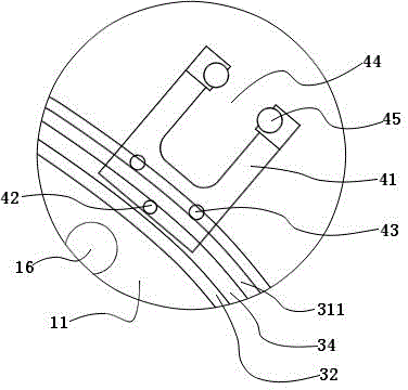
[0020] Each side plate 11 is respectively equipped with two gears 21 and a guide mechanism. The g...


PUM


Abstract

The invention discloses a cyclic type mold-clamping mechanism which comprises a chain, a rack and mold-clamping grabbing pieces, wherein gears are arranged at two ends of the rack; a chain frame is arranged on two gears; three mold-clamping grabbing pieces are provided and fixed on the chain; the three mold-clamping grabbing pieces are arranged on the chain at equal intervals; and a guide mechanism is arranged on the rack and used for enabling the mold-clamping grabbing piece to move in a circular arc direction between the two gears under the driving of the chain. According to the cyclic type mold-clamping mechanism, when a motor drives the chain to move circularly, the three mold-clamping grabbing pieces can clamp a mold cyclically and continuously.

Description

technical field [0001] The invention relates to a mold clamping mechanism, in particular to a mold clamping mechanism for foaming molds in foaming equipment. Background technique [0002] Under the prior art, foaming equipment is already a highly automated equipment. However, there are still many places in the production process that require manpower access. For example, manual work is required to close the mold after injection. Contents of the invention [0003] The problem to be solved by the invention: the automation of mold clamping operation. [0004] In order to solve the above problems, the scheme adopted by the present invention is as follows: [0005] A circulating mold clamping mechanism, comprising a chain, a frame and a mold clamping grab; gears are arranged at both ends of the frame; the chain is erected on the two gears; the mold clamping grab has three one, is fixed on the chain; three mold clamping grabs are equidistant on the chain; the frame is provid...

Claims


Application Information

Patent Timeline
Patent Type & Authority Applications(China)
IPC IPC(8): B29C33/20B29C44/34
Inventor 汤德斌孙敏段宗军
Owner ANHUI KINGPOWER EQUIP & MOLD MFR
Why Eureka
Try Eureka