
Dynamic grid generation method, generation device, polymerization method and polymerization device

A dynamic grid and generation device technology, applied in the field of communication, can solve problems such as data deviation and slow efficiency, and achieve the effect of meeting real-time requirements

Active Publication Date: 2015-09-23
GCI SCI & TECH
View PDF5 Cites 6 Cited by
  • Summary
  • Abstract
  • Description
  • Claims
  • Application Information

AI Technical Summary

Problems solved by technology

[0007] In the first method, the data needs to be stored in the reference point database first. Since the surface area of ​​the earth is about 5.1 square kilometers, assuming that the defined grid area is 0.1 square kilometers, the amount of data that needs to be stored in advance reaches 5.1 billion. If you want to define grids of other sizes, you need to calculate and store the range of each grid; and when the amount of data becomes larger and larger, more and more data will be stored, and the efficiency will become slower and slower
[0008] The second method, since each grid range is obtained by dividing the current display area by the number of grids, the grid range will change according to the current display area (the same display level display area will change), so the aggregated data There will be a large deviation

Method used


Image

  • Dynamic grid generation method, generation device, polymerization method and polymerization device
  • Dynamic grid generation method, generation device, polymerization method and polymerization device
  • Dynamic grid generation method, generation device, polymerization method and polymerization device

Examples


Embodiment 1

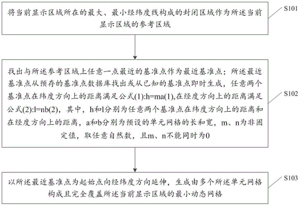
[0053] see figure 1 , is a schematic flowchart of the first embodiment of a method for generating a dynamic grid provided by the present invention, including the following steps:

[0054]S101. Take the closed area formed by the maximum and minimum latitude and longitude lines where the current display area is located as a reference area of ​​the current display area.

[0055] Among them, the dynamic grid generation method of the present invention is to generate a dynamic grid based on the current display area, and the current display area can be an area of ​​regular or irregular graphics. The maximum longitude line, the maximum latitude line, the minimum longitude line and the minimum latitude line, and these four lines intersect to form a closed area, which is used as the reference area of ​​the current display area.

[0056] In order to more clearly describe the reference area in step S101, as Figure 4a As shown, it is a model schematic diagram of a dynamic grid generatio...

Embodiment 2

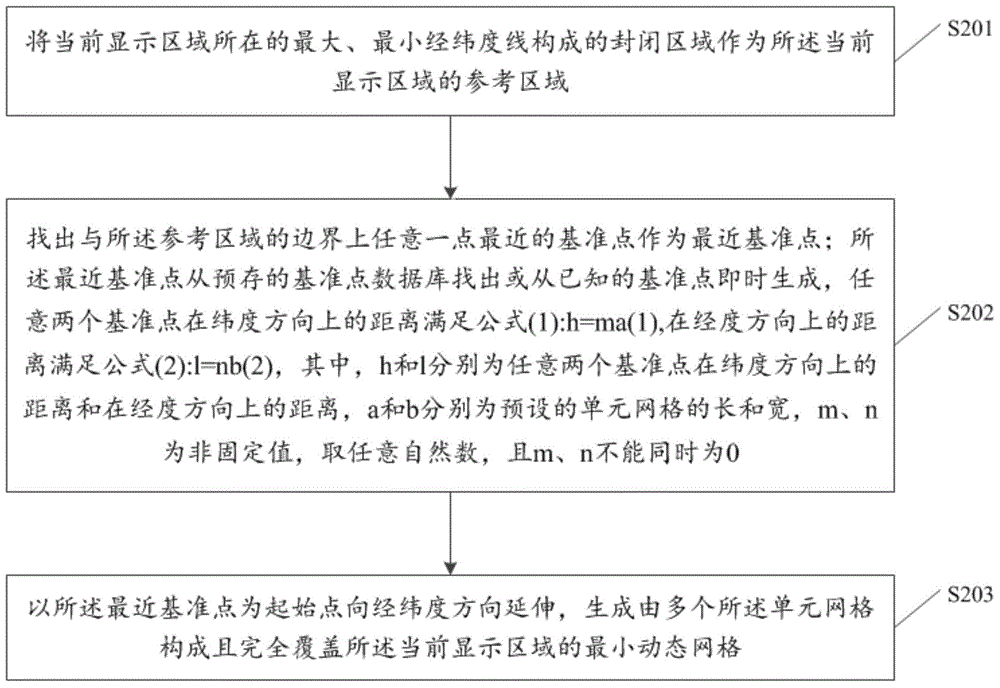
[0096] see figure 2 , is a schematic flowchart of the second embodiment of a method for generating a dynamic grid provided by the present invention, including the following steps:

[0097] S201. Take the closed area formed by the maximum and minimum latitude and longitude lines where the current display area is located as a reference area of ​​the current display area.

[0098] S202. Find a reference point closest to any point on the boundary of the reference area as the closest reference point.

[0099] The nearest reference point is found from the pre-stored reference point database or generated instantly from known reference points, the distance between any two reference points in the longitude direction is: h=ma, and the distance in the latitude direction is: l= nb,

[0100] Among them, h and l are the distance between any two reference points in the longitude direction and the latitude direction respectively, a and b are the length and width of the preset unit grid res...

Embodiment 3

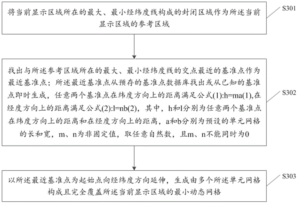
[0105] see image 3 , is a schematic flowchart of the third embodiment of a method for generating a dynamic grid provided by the present invention, including the following steps:

[0106] S301. Take the closed area formed by the maximum and minimum latitude and longitude lines where the current display area is located as a reference area of ​​the current display area.

[0107] S302. Find the closest reference point to the intersection point of the maximum and minimum latitude and longitude lines where the reference area is located as the nearest reference point;

[0108]The nearest reference point is found from the pre-stored reference point database or generated instantly from known reference points, the distance between any two reference points in the longitude direction is: h=ma, and the distance in the latitude direction is: l= nb,

[0109] Among them, h and l are the distance between any two reference points in the longitude direction and the latitude direction respecti...


PUM


Abstract

The invention discloses a dynamic grid generation method. The dynamic grid generation method comprises the following steps: taking a sealed region formed by maximum and minimum longitude and latitude lines of a current display region as a reference region of the current display region; finding out a reference point closest to any point of the reference region as a closest reference point, wherein the closest reference point is found from a pre-stored reference point database or is instantly generated from the known reference points; and taking the closest reference point as a starting point for extending in the longitude and latitude directions to generate a minimum dynamic grid which is composed of a plurality of unit grids and completely covers the current display region. The invention further discloses a dynamic grid generation device, and a polymerization method and device based on the dynamic grid. With the adoption of the embodiment of the invention, the problems in a grid clustering algorithm that a lot of data need to be stored, the data processing speed is low and the polymerization errors are great can be effectively solved.

Description

technical field [0001] The present invention relates to the field of communication technology, in particular to a method and device for generating a dynamic grid, and an aggregation method and device based on the dynamic grid. Background technique [0002] Clustering is the process of grouping a collection of physical or abstract objects into classes of similar objects. Clustering algorithms can be divided into the following categories: partitioning methods, hierarchical methods, density-based methods, grid-based methods, and model-based methods. Among them, grid clustering algorithms have a very wide range of applications in geology and geography. application. [0003] The grid clustering algorithm adopts the grid data structure, divides the space into multiple units, and these units form a grid structure, and all clustering operations are performed on the grid. In the grid clustering algorithm, the range of each grid should be determined or defined first, and then the ag...

Claims


Application Information

Patent Timeline
IPC IPC(8): G06K9/62
CPCG06F18/2323
Inventor 张铁山
Owner GCI SCI & TECH
Learn More