
Electro-optical crystal electro-optical factor measure method and device

A technology of electro-optic crystals and electro-optic coefficients, applied in the direction of measuring devices, measuring electricity, measuring electrical variables, etc., can solve the problems of large measurement errors, complicated adjustments, and difficulty in accurately determining the position of extreme values, and achieve the image of the measurement process, the instrument The effect of simple equipment and easy adjustment

Active Publication Date: 2015-09-23
NANKAI UNIV
View PDF5 Cites 12 Cited by
  • Summary
  • Abstract
  • Description
  • Claims
  • Application Information

AI Technical Summary

Problems solved by technology

[0009] 1. The extreme value measurement method needs to measure the voltage-light intensity curve with a small voltage interval. Due to the influence of the stability of the light intensity of the laser source, the environment and the measurement conditions, the error is large, and it is difficult to accurately determine the position of the extreme value.
[0010] 2. The frequency doubling measurement method is more accurate, but it has higher requirements for adjustment, it is difficult to adjust to the best state, and more equipment is required
[0011] 3. The optical communication simulation method can only be used to roughly measure the half-wave voltage. Due to the difference in human senses, the measurement error is large
[0012] 4. The comparison method and the interference compensation method use many components and equipment, and the adjustment is complicated and difficult to be practical

Method used

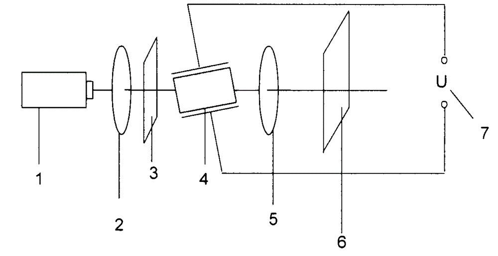

Image

  • Electro-optical crystal electro-optical factor measure method and device
  • Electro-optical crystal electro-optical factor measure method and device
  • Electro-optical crystal electro-optical factor measure method and device

Examples


Embodiment 1

[0027] 1. Theoretical analysis: The electro-optic crystal to be tested is a lithium niobate crystal with a size of X×Y×Z=9mm×9mm×18.5mm (X, Y, Z represent crystallographic directions, the same below), doped with 6.5mol% magnesium , by the electro-optic coefficient γ to be measured 22 Determine the direction of the applied voltage as the x-axis direction of the crystal. According to the electro-optic effect and the theory of the refractive index ellipsoid, it can be obtained that the inductive main axes x', y' are rotated 45° relative to the original axes x, y, and z' is the same as the z-axis.

[0028] In the case of applying DC voltage, at any angle (θ, φ) (θ is the angle between the laser propagation direction and the z' axis, φ is the angle between the projection of the laser propagation direction on the x'oy' plane and the x' axis ) The phase difference due to birefringence when the incident laser passes through the crystal is:

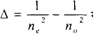
[0029] δ ...

Embodiment 2

[0046] 1. Theoretical analysis: The electro-optic crystal to be tested is a nominally pure lithium niobate crystal with a size of X×Y×Z=9mm×9mm×18.8mm. The electro-optic coefficient γ to be measured is 22 Determine the direction of the applied voltage as the x-axis direction of the crystal. According to the electro-optic effect and the theory of the refractive index ellipsoid, it can be obtained that the inductive main axes x', y' are rotated 45° relative to the original axes x, y, and z' is the same as the z-axis.

[0047] In the case of applying DC voltage, at any angle (θ, φ) (θ is the angle between the laser propagation direction and the z' axis, φ is the angle between the projection of the laser propagation direction on the x'oy' plane and the x' axis ) The phase difference due to birefringence when the incident laser passes through the crystal is:

[0048] δ 1 = π n ...

Embodiment 3

[0065] 1. Theoretical analysis: The electro-optic crystal to be tested is a nominally pure lithium niobate crystal with a size of X×Y×Z=9mm×9mm×9.8mm. The electro-optic coefficient γ 22 Determine the direction of the applied voltage as the x-axis direction of the crystal. According to the electro-optic effect and the theory of the refractive index ellipsoid, it can be obtained that the inductive main axes x', y' are rotated by 45 relative to the original axes x, y, and z' is the same as the z-axis.

[0066] In the case of applying DC voltage, at any angle (θ, φ) (θ is the angle between the laser propagation direction and the z' axis, φ is the angle between the projection of the laser propagation direction on the x'oy' plane and the x' axis ) The phase difference due to birefringence when the incident laser passes through the crystal is:

[0067] δ 1 = π n ...


PUM

PropertyMeasurementUnit
Electro-optic coefficientaaaaaaaaaa

Abstract

An electro-optical crystal electro-optical factor measure method and device comprises the following steps: a laser with visible wave bands passes a polarizing lens, a ground glass, a to be tested electro-optical crystal and a polarization analyzer in sequence, and a white screen receives an exit light spot and an interference pattern formed by diffusion light caused by the ground glass; a polarization direction of the polarizing lens and the polarization analyzer is vertical, and an adjustable DC voltage is applied to the to be tested electro-optical crystal; firstly, select a property laser entrance angle ([theta]0, [phi]0) through theory analysis, wherein the ([theta]0, [phi]0) refer to angles between an entrance laser propagation direction and each electric induction main shaft of the to be tested electro-optical crystal; in measurement, the DC voltage applied to the to be tested electro-optical crystal is adjusted to OV, an angle between the to be tested electro-optical crystal and the entrance laser is tuned, so the exit light spot can fall on a dark zone, corresponding to the entrance angle ([theta]0, [phi]0), in the interference pattern; the DC voltage is gradually boosted and the exit light spot position in the process does not change, and the interference pattern will change; when the exit light spot fall on next adjacent dark zone on the interference pattern again, the DC voltage value U is recorded; the corresponding electro-optical factor can be obtained through theory calculation.

Description

technical field [0001] The invention belongs to the technical field of photoelectric measurement, and in particular relates to a method and a device for measuring the electro-optic coefficient of an electro-optic crystal. Background technique [0002] Due to its linear electro-optic effect, electro-optic crystals have been widely used in the field of laser technology, mainly in electro-optic modulation, electro-optic Q-switching, etc. The accurate measurement of electro-optic coefficients of electro-optic crystals has important guiding significance for the design and use of these devices. [0003] At present, there are mainly the following methods and devices for measuring the electro-optic coefficient of electro-optic crystals: [0004] 1. Extreme value measurement method. Make the output stable laser incident on the crystal placed between the orthogonal polarizers, the laser propagation direction is parallel to a certain axis of the crystal, apply an adjustable DC voltage...

Claims


Application Information

Patent Timeline
IPC IPC(8): G01R31/00G01M11/02
Inventor 孙军许京军张玲商继芳李清连
Owner NANKAI UNIV
Learn More