Automobile engine fan cover
A technology for automobile engine and windshield, which is applied in the direction of engine components, machine/engine, engine cooling, etc., can solve problems such as easy deformation, and achieve the effect of increasing strength and improving installation space.
Inactive Publication Date: 2015-09-23
东风(十堰)非金属部件有限公司
View PDF3 Cites 0 Cited by
- Summary
- Abstract
- Description
- Claims
- Application Information
AI Technical Summary
Problems solved by technology
[0009] In order to solve the problem of easy deformation of the fan installation surface transition large plane structure and the firm failure of the butt joint with the fan, the present invention proposes an automobile engine windshield
Method used
View moreImage
Smart ImageViewing Examples
Examples
Embodiment Construction
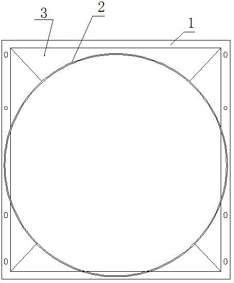
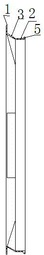
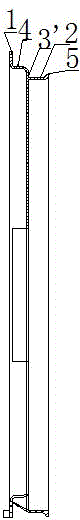
[0022] The present invention as image 3 shown.
[0023] The automobile engine windshield includes the installation surface 1, on which the guide surface 4 is vertically arranged upwards, and the guide surface 4 is connected with the fan interface 2, wherein the large connecting plane between the guide surface 4 and the fan interface 2 is a plane 3'.
[0024] The height of the guide surface 4 is 3-5 mm.
[0025] An anti-slip opening 5 is provided outside the fan interface 2 .
Login to view more PUM
Property | Measurement | Unit |
---|---|---|
Height | aaaaa | aaaaa |
Abstract
The invention provides an automobile engine fan cover comprising an installation surface. A guide surface is upwardly arranged on the installation surface in a vertical way; the guide surface is connected with a docking interface of a fan; a large surface of the connection between the guide surface and the fan is a plane; the height of the guide surface is 3 to 5mm; and an anti-falling port is arranged outside the fan docking interface. An inclined plane is changed into the vertical guide surface, equaling increase of four reinforcing ribs after connection, so installation space is improved and peripheral strength is greatly enhanced; even in high temperature environment for long time, deformation of the fan cover due to heat can be prevented; enough installation space is provided by the guide surface with 3 to 5mm height and effects of reinforcing ribs are enhanced; and firmness of docking between the engine and the fan cover is enhanced by the use of the anti-falling port. After installation and use, the deformation of the installation surface is narrowed from about 7mm to 1 mm; and the assembling hole center position is within 1mm tolerance, so assembling difficulty is overcome.
Description
technical field [0001] The invention relates to automobile parts, in particular to an automobile engine windshield. Background technique [0002] The windshield of the automobile engine is installed outside the heater tank, and it is in a hot environment for a long time, and it is easy to deform when heated. At present, most of the shrouds are designed to transition from the installation surface to the fan installation surface with a slope structure, which is a large flat structure, easy to deform, and the deformation of the bottom surface is about 7mm. like figure 1 , 2 shown. In the figure, the large planar structure connecting the installation surface 1 and the fan interface 2 is an inclined surface 3, wherein the installation surface 1 is easily deformed, and the fan interface 2 is provided with an anti-slip opening 5. After the deformation of the installation surface 1, the center position of the assembly hole is shifted by about 3 mm, which makes it difficult to as...
Claims
Login to view more Application Information
Patent Timeline
![application no application](https://static-eureka-patsnap-com.libproxy1.nus.edu.sg/ssr/23.2.0/_nuxt/application.06fe782c.png)
IPC IPC(8): F01P5/06F01P11/10
Inventor 赵炀郑秋锐文汉防杨青龙
Owner 东风(十堰)非金属部件有限公司
- R&D Engineer
- R&D Manager
- IP Professional
Why Eureka
- Industry Leading Data Capabilities
- Powerful AI technology
- Patent DNA Extraction
Try Eureka
Browse by: Latest US Patents, China's latest patents, Technical Efficacy Thesaurus, Application Domain, Technology Topic.
© 2024 PatSnap. All rights reserved.Legal|Privacy policy|Modern Slavery Act Transparency Statement|Sitemap