Cable clamping assembly for binding beam type cable

A cable and bundle-shaped technology, which is applied in the field of clamping components for bundling bundle-shaped cables, can solve the problems of inconvenient use, tangling into a mess, and hindering the use of the next tying.

Active Publication Date: 2015-09-16
JIANGSU XINDA COMM TECH
View PDF9 Cites 4 Cited by
  • Summary
  • Abstract
  • Description
  • Claims
  • Application Information

AI Technical Summary

Problems solved by technology

[0003] Existing wired devices have long cables, which are easily tangled into a mess when carried and stored, which is quite inconvenient to use
When these electrical appliances with cables leave the factory, their single cables are repeatedly folded to form a bundle of cables, and then tied on the bundle of cables with cable ties, cables or rubber bands. Disassemble the cable ties, cables or rubber bands, so the cable ties, cables and rubber bands are easily lost, which hinders the use of the next ligation
[0004] The existing long tail clip includes a clamping piece and two clamping handles; the clamping piece includes two splints made in one piece, and the two sides of the end plate body of each splint are bent and rolled back toward the outside of the splint to form two pin holes; Each clamping handle is made of steel wire, and each clamping handle includes two load-bearing parts. The two ends of the two load-bearing parts are bent to form two pins, and each pin is inserted into a corresponding pin hole; The structure allows the long tail clip to be clamped on a single cable of a wired device with its two splints, but it still cannot be used to tidy up the cable, so its structure still has room for improvement

Method used


Image

  • Cable clamping assembly for binding beam type cable
  • Cable clamping assembly for binding beam type cable
  • Cable clamping assembly for binding beam type cable

Examples


Embodiment Construction

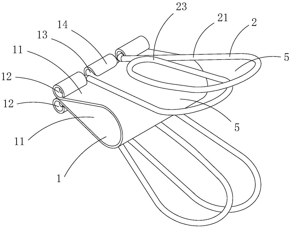
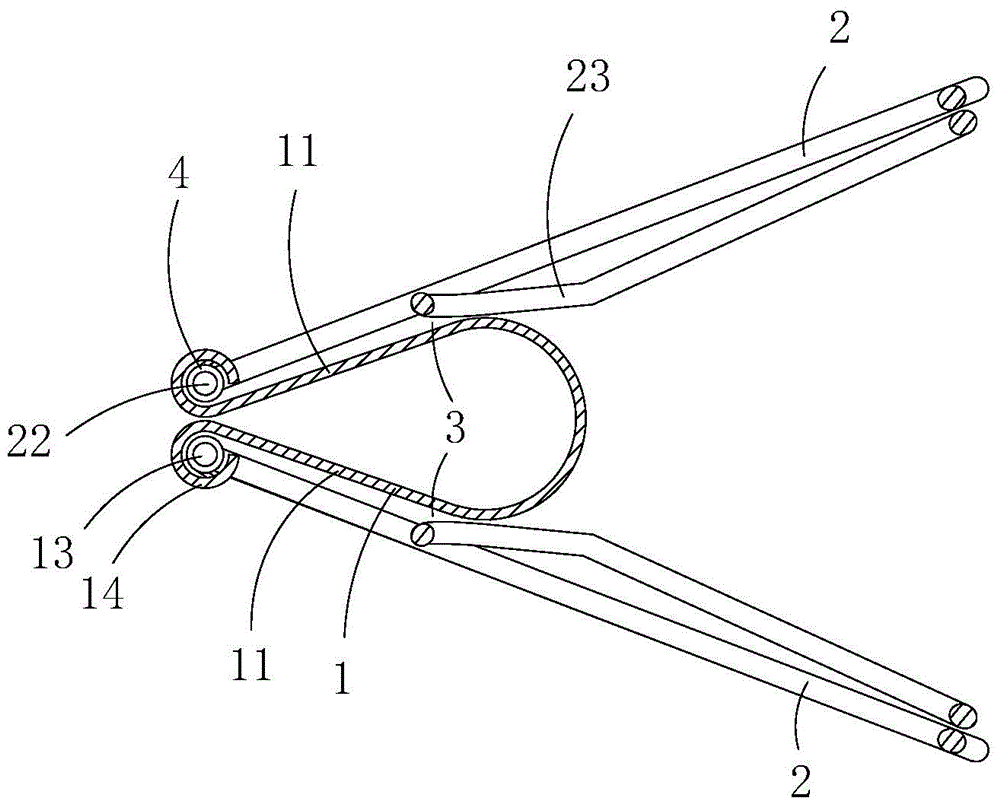
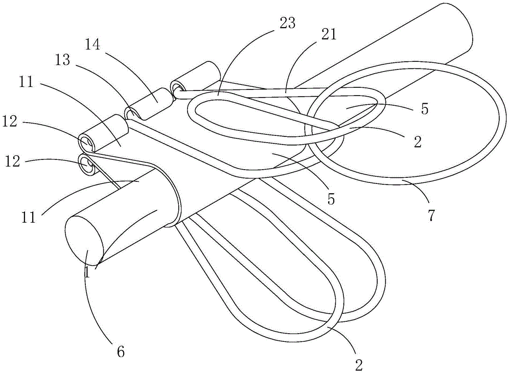
[0011] Figure 1 to Figure 3 A specific embodiment of the invention is shown in which, figure 1 It is a schematic diagram of a three-dimensional structure of the present invention; figure 2 yes figure 1 A cutaway view of the long tail clip shown; image 3 yes figure 1 A schematic diagram of the application of the long tail clip shown.

[0012] Present embodiment is a kind of long tail folder, see Figure 1 to Figure 2 , including a clamping piece 1 and two clamping handles 2; the clamping piece includes two splints 11 made in one piece, and the two sides of each splint end plate are bent and rolled back toward the outside of the splint to form two pin holes 12; each The clamping handle is made of steel wire, and each clamping handle includes two load-bearing parts 21. The two ends of the two load-bearing parts bundled cables are bent to form two pins 22, and each pin is inserted into a corresponding pin. In the hole; the middle part of each clamp handle is wound to form...


PUM


Abstract

The invention discloses a long tail clamp which comprises a clamping connection piece and two clamping handles, wherein the clamping connection piece comprises two clamping plates which are integrally formed; ends of two sides of a plate body at the tail end of each clamping plate are bent and unreeled towards the direction of outer side of each clamping plate to form two pin holes; each clamping handle is formed by a steel wire in a winding way, and comprises two bearing parts, two tail ends of the two bearing parts are bent to form two pin columns, and each pin column is inserted into each corresponding pin hole; the middle part of each clamping handle is wound to form a limiting part, each pin hole is provided with a torsion spring used for providing reset elastic force for each corresponding clamping handle, and each clamping handle enables the middle part of each limiting part to be propped against the outer wall of each clamping plate under the action of reset elastic force of each torsion spring; one end, close to pin holes, of each limiting part and the outer wall of each corresponding clamping plate form a guiding notch; each limiting part, bearing parts and the outer wall of each corresponding clamping plate are combined to form a sleeve hole. The long tail clamp has the advantage of convenience in use, and can bundle up cables tidily.

Description

[0001] This application is a divisional application with the filing date of "July 08, 2013", the application number of "2013102842777", and the name of "clamp assembly for bundling bundled cables". technical field [0002] The technical field of clip structure design of the present invention, in particular relates to a cable clip assembly for bundling bundled cables. Background technique [0003] Existing wired devices all have relatively long cables, which are easily tangled into a mess when being carried and stored, which is quite inconvenient to use. When these electrical appliances with cables leave the factory, their single cables are repeatedly folded to form a bundle of cables, and then tied on the bundle of cables with cable ties, cables or rubber bands. Disassemble the cable tie, cable or rubber band, so the cable tie, cable and rubber band are easily lost, which hinders the next ligation. [0004] The existing long tail clip includes a clamping piece and two clamp...

Claims


Application Information

Patent Timeline
Patent Type & Authority Applications(China)
IPC IPC(8): B65D67/02
Inventor 不公告发明人
Owner JIANGSU XINDA COMM TECH
Why Eureka
Try Eureka