
Single-phase power saving compensation control box

A compensation control and power-saving control technology, applied in reactive power compensation, reactive power adjustment/elimination/compensation, circuits, etc., to solve the problems of power waste, large power consumption, and large power loss of transmission lines for equipment that cannot be used. , to reduce line loss, improve power quality, and ensure the effect of normal operation

Inactive Publication Date: 2015-09-02
GUANGXI UNIV
View PDF4 Cites 2 Cited by
  • Summary
  • Abstract
  • Description
  • Claims
  • Application Information

AI Technical Summary

Problems solved by technology

[0002] The power-saving compensation control box is suitable for all kinds of household appliances. It is very convenient, time-saving and labor-saving. It is an essential electronic device in modern people's life. Various types of power-saving compensation control boxes can be used in both households and ordinary households. With the continuous development of my country's economy and the continuous improvement of people's living standards, every household has added a lot of household appliances. The place of activity needs to consume a lot of electric energy every day, the power loss of the transmission line is large, and the best performance of the electric equipment cannot be used and a large amount of electric energy is wasted. Improve the socket on the computer, develop and design an energy-saving compensation control box that can reduce the power loss of electrical equipment and perform reactive power compensation for the power of the power line. In the environment where the country actively advocates energy conservation and emission reduction, it has a very important practical significance

Method used


Image

  • Single-phase power saving compensation control box
  • Single-phase power saving compensation control box

Examples


Embodiment Construction

[0017] The technical solutions in the embodiments of the present invention will be clearly and completely described below in conjunction with the accompanying drawings in the examples of the present invention. Obviously, the described embodiments are only some of the embodiments of the present invention, not all of them. Based on the embodiments of the invention, all other embodiments obtained by persons of ordinary skill in the art without creative efforts fall within the protection scope of the present invention.

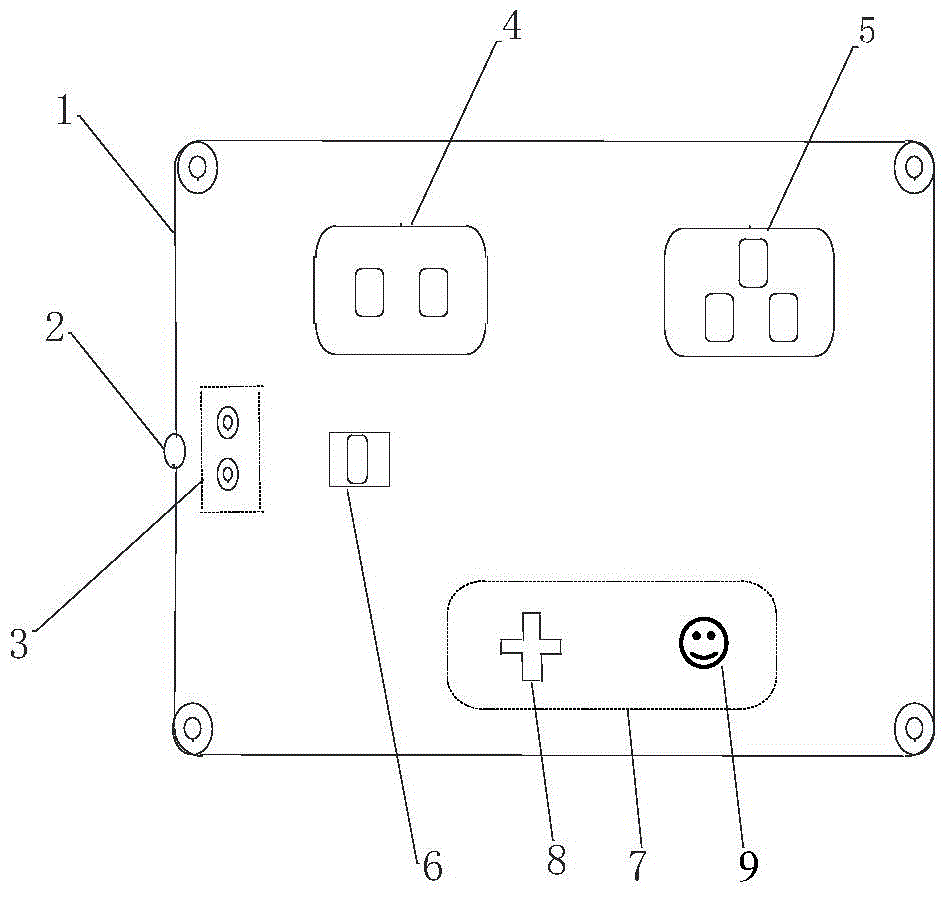
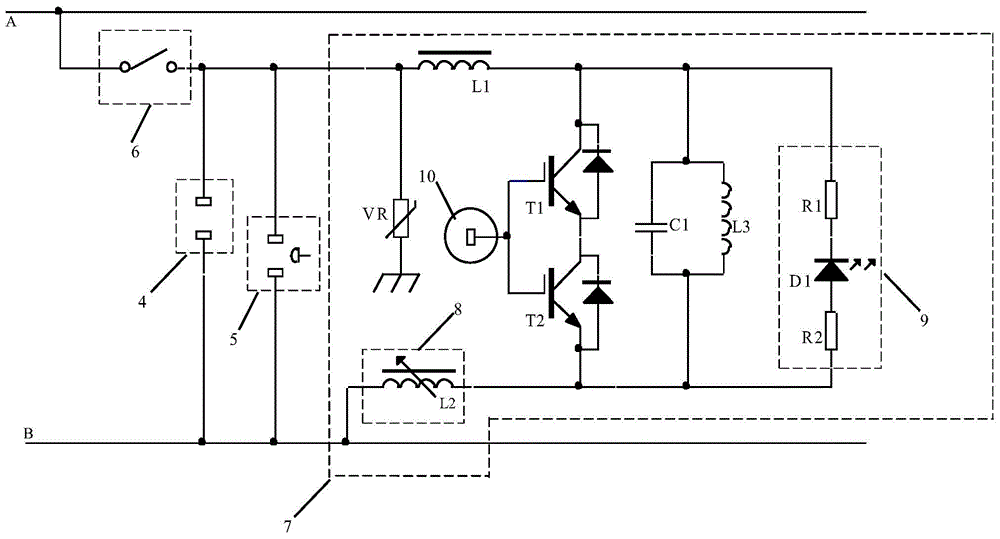
[0018] Such as figure 1 As shown, a single-phase power-saving compensation control box includes a control box housing 1 and a power input hole 2, and also includes a terminal post 3 and a power-saving control module 7 arranged inside the control box housing 1, and is arranged on the control box. The main power switch 6 on the box housing 1, the single-phase power jack 4 and the three-phase power jack 5, one end of the main power switch 6 is connected to the live w...


PUM


Abstract

The invention belongs to the electronic plug-in connecting device and power saving compensation control technical field, and specifically relates to a single-phase power saving compensation control box comprising a control box housing and a power input hole, and a terminal and a power saving control module arranged in the control box housing, and a power total switch, a single-phase power supply plug hole and a three-phase power supply plug hole arranged on the control box housing; one end of the power total switch is connected with a live-line A; the single-phase power supply plug hole and the three-phase power supply plug hole are connected in parallel with the power saving control module, and one end after parallel connection is connected with the other end of the power total switch, and the other end after the parallel connection between the single-phase power supply plug hole, the three-phase power supply plug hole and the power saving control module is connected with a zero-line B. the single-phase power saving compensation control box is very good in lightning protection effect, can improve power factors, remove harmonic waves, and save power, thus reducing voltage fluctuation in a power supply line, and recuing line loss.

Description

technical field [0001] The invention belongs to the technical field of connection equipment for electronic plug-in and power-saving compensation control, and in particular relates to a single-phase power-saving compensation control box. Background technique [0002] The power-saving compensation control box is suitable for all kinds of household appliances. It is very convenient, time-saving and labor-saving. It is an essential electronic device in modern people's life. Various types of power-saving compensation control boxes can be used in both households and ordinary households. With the continuous development of my country's economy and the continuous improvement of people's living standards, every household has added a lot of household appliances. The place of activity needs to consume a lot of electric energy every day, the power loss of the transmission line is large, and the best performance of the electric equipment cannot be used and a large amount of electric energy ...

Claims


Application Information

Patent Timeline
Patent Type & Authority Applications(China)
IPC IPC(8): H02J3/01H02J3/18H01R13/66H01R13/719
CPCY02E40/30Y02E40/40
Inventor 龙邹
Owner GUANGXI UNIV
Learn More