image forming device

A technology of image and retreat position, which is applied in the direction of electrical recording technology using charge graphics, equipment and instruments of electrical recording technology using charge graphics, etc.

Active Publication Date: 2019-07-09
BROTHER KOGYO KK
View PDF5 Cites 0 Cited by
  • Summary
  • Abstract
  • Description
  • Claims
  • Application Information

AI Technical Summary

Problems solved by technology

[0005] However, in the above-mentioned technology, when the opening and closing member is opened, the interlock switch can only be pressed by inserting a rod or the like through the hole.

Method used


Image

  • image forming device
  • image forming device
  • image forming device

Examples


Embodiment Construction

[0051] [First Embodiment]

[0052] Hereinafter, the first embodiment of the present invention will be described in detail with reference to the accompanying drawings as appropriate. In addition, in the following description, first, the overall configuration of a color printer 1 as an example of an image forming apparatus will be described, and then the characteristic parts of the present invention will be described in detail.

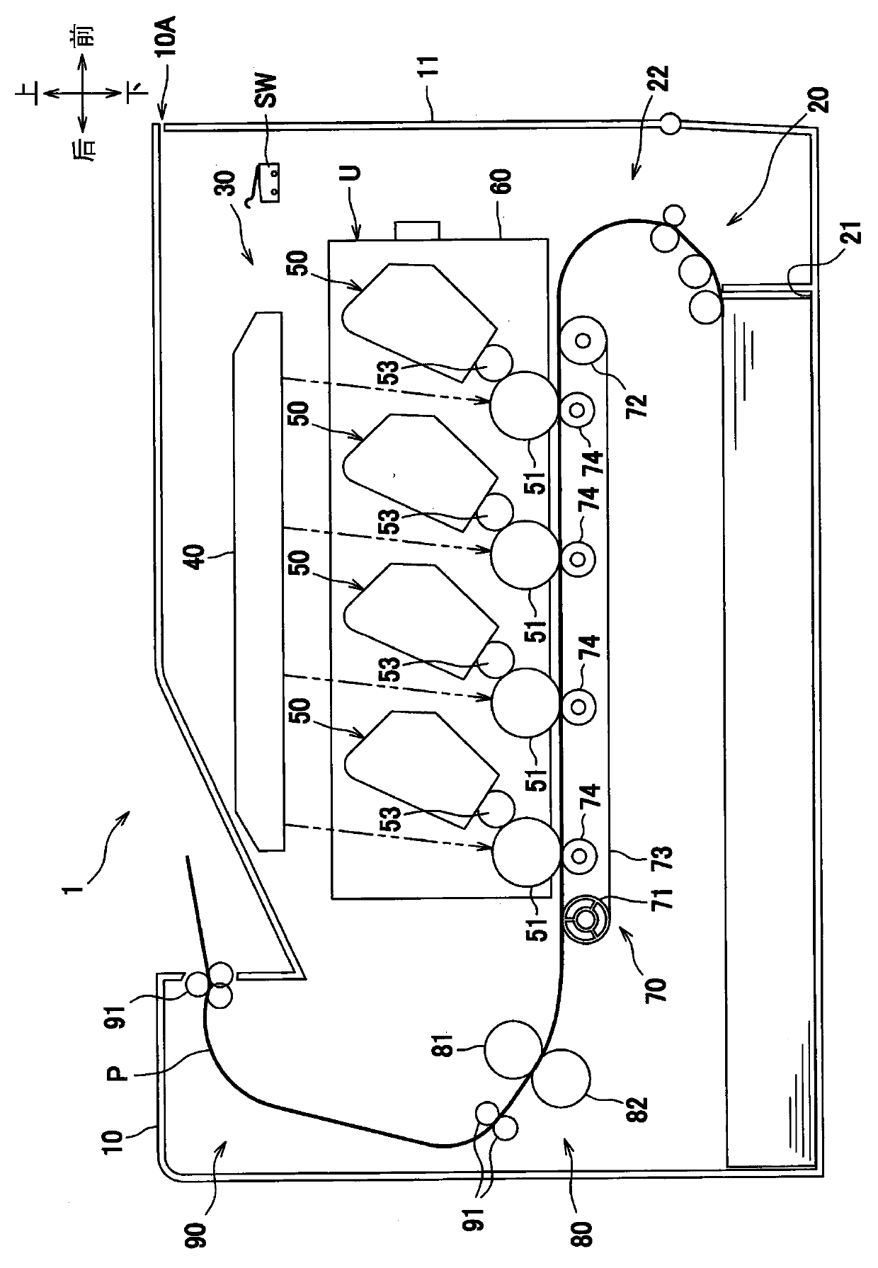
[0053] In the following description, the directions are described based on the user's directions when using a color printer. That is, in figure 1 Among them, the right side facing the paper is set as "front side (near side)", the left side is set as "rear side (rear side)" facing the paper, the back side is set as "right side" facing the paper, and the For the paper surface, the front side is set to "left side". In addition, let the up-down direction be "up-down direction" toward the paper surface.

[0054] Such as figure 1 As shown, the color prin...


PUM


Abstract

An image forming apparatus includes a casing having a first opening and a second opening. The first and second openings each extend between an interior of the casing and an exterior of the casing. A cover has a close position in which the cover covers the first opening and the second opening, and an open position in which cover does not cover the first opening and the second opening. A shutter has a shielding position in which the shutter covers the second opening, and a retracted position. The shutter is operably connected to the cover so as to move between the shielding position and the retracted position in response to movement of the cover. A protrusion extends from the cover, and the protrusion extends through the second opening when the cover is in the close position and the shutter is in the retracted position.

Description

technical field [0001] The present invention relates to an image forming apparatus provided with an interlock switch inside a frame. Background technique [0002] Conventionally, in an image forming apparatus, there is a technique in which an interlock switch is provided in a casing, and ON and OFF of the interlock switch are switched by opening and closing a switch member. Specifically, a protruding pressing part is provided on the inner surface of the opening and closing part. When the opening and closing part is closed, the pressing part enters into the hole provided on the frame body, and the interlock switch arranged inside it is activated. Press (for example, Patent Document 1). [0003] In addition, in the image forming apparatus disclosed in Patent Document 1, between the hole of the frame and the interlock switch, a restricting member movable in a direction intersecting the direction through which the hole penetrates is provided. The holes have small openings. In...

Claims


Application Information

Patent Timeline
Patent Type & Authority Patents(China)
IPC IPC(8): G03G15/00
CPCG03G21/1633G03G2221/169H01H9/22H01H21/06
Inventor 青井洋介
Owner BROTHER KOGYO KK
Why Eureka
Try Eureka