
Jacquard machine assembly device

A unit and insert technology, applied in jacquard machines, textiles, textiles and papermaking, etc., can solve problems such as difficulty in controlling the spring force of the vertical hook spring, high contact pressure of the moving iron shaft, wear and tear of the vertical hook spring, etc., to achieve The effect of overcoming control difficulties, avoiding failure, and improving production efficiency

Active Publication Date: 2015-09-02
JIANGSU S&S INTELLIGENT SCI & TECH CO LTD
View PDF7 Cites 2 Cited by
  • Summary
  • Abstract
  • Description
  • Claims
  • Application Information

AI Technical Summary

Problems solved by technology

[0002] At present, the most widely used jacquard machine is to use the spring pressure and the reed pressure when the carabiner is pushed up to realize the reciprocating movement of the moving iron. When the components are working, the force of the spring and the reed of the carabiner acting on the moving iron is outward relative to the component. , so that when the moving iron rotates around the iron shaft, the inner contact pressure of the moving iron shaft is relatively large and the force area is small, resulting in increased wear of the moving iron shaft, difficulty in controlling the spring force of the vertical hook reed, and serious wear and tear failure of the vertical hook reed , and there are many types of parts in this structural component, the structure of each part is complex, the assembly of parts is difficult, the corresponding cost is high, the failure rate is high, the maintenance cost is high, and the maintenance cycle is shortened

Method used


Image

  • Jacquard machine assembly device
  • Jacquard machine assembly device

Examples


Embodiment Construction

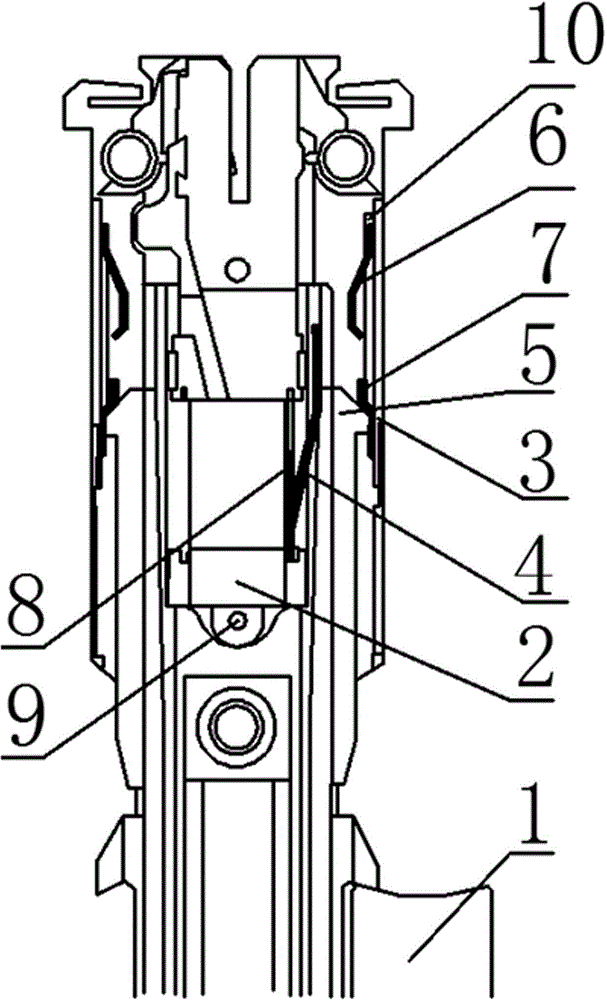
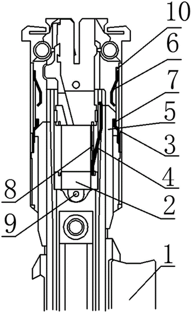
[0013] With reference to the accompanying drawings, a jacquard machine component device includes a broach 1, an electromagnet 2, a splint 3, a return spring piece 4, a moving iron vertical hook 5, an auxiliary suction spring piece 6 and a return spring piece hook 7, and the broach 1 is installed on the jacquard machine, the electromagnet 2 is installed on the splint 3, the electromagnet is fixed by the positioning pin 9, the return spring piece 4 is installed on the electromagnet 2, and the moving iron vertical hook 5 is installed on the Between the two splints 3, the moving iron vertical hook 5 is driven by the broach 1 to slide in the T-shaped groove formed by the two splints 3, and the moving iron vertical hook 5 is injected with a soft magnetic insert inside, and the soft magnetic One side of the insert is exposed outside, the splint 3 is provided with a return spring leaf hook 7, and an auxiliary suction spring leaf 6 is installed above the return spring leaf hook 7.

[0...


PUM


Abstract

The invention relates to the technical field of textile machinery, in particular to a jacquard machine assembly device. The jacquard machine assembly device comprises a broach, electromagnets, clamping plates, a reset spring piece, a moving iron vertical hook, suction assistance spring pieces and reset spring hooks. The broach is arranged on a jacquard machine, the electromagnets are arranged on the clamping plates, the reset spring is arranged on the electromagnet, and the vertical moving iron hook is arranged between the two clamping plates. The vertical moving iron hook is driven by the broach to slide in a T-shaped groove formed by the two clamping plates. A soft magnetic insert is arranged in the vertical moving iron hook. The reset spring hooks are arranged on the clamping plates, and the suction assistance spring pieces are arranged above the reset spring hooks. By means of the jacquard machine assembly device, a moving iron shaft, a moving iron pressure spring, moving iron and a tongue spring which are prone to abrasion are omitted, so that component failures caused by abrasion of the moving iron shaft, the moving iron pressure spring, the moving iron and the tongue spring are eliminated, the component structure is changed, the service lives of the components are prolonged, the machining and assembling difficulty of all components is reduced, production cost is reduced, the failure occurrence rate and maintenance cost are reduced, and the production efficiency of the jacquard machine is improved.

Description

technical field [0001] The invention relates to the technical field of textile machinery, in particular to a jacquard machine component device. Background technique [0002] At present, the most widely used jacquard machine is to use the spring pressure and the reed pressure when the carabiner is pushed up to realize the reciprocating movement of the moving iron. When the components are working, the force of the spring and the reed of the carabiner acting on the moving iron is outward relative to the component. , so that when the moving iron rotates around the iron shaft, the inner contact pressure of the moving iron shaft is relatively large and the force area is small, resulting in increased wear of the moving iron shaft, difficulty in controlling the spring force of the vertical hook tongue spring, and serious wear and tear failure of the vertical hook tongue spring , and there are many types of parts in the structural assembly, the structure of each part is complex, the ...

Claims


Application Information

Patent Timeline
Patent Type & Authority Applications(China)
IPC IPC(8): D03C3/36
Inventor 宋日升
Owner JIANGSU S&S INTELLIGENT SCI & TECH CO LTD
Learn More