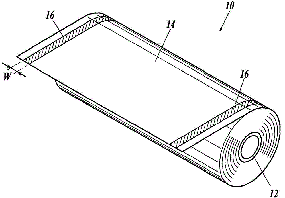
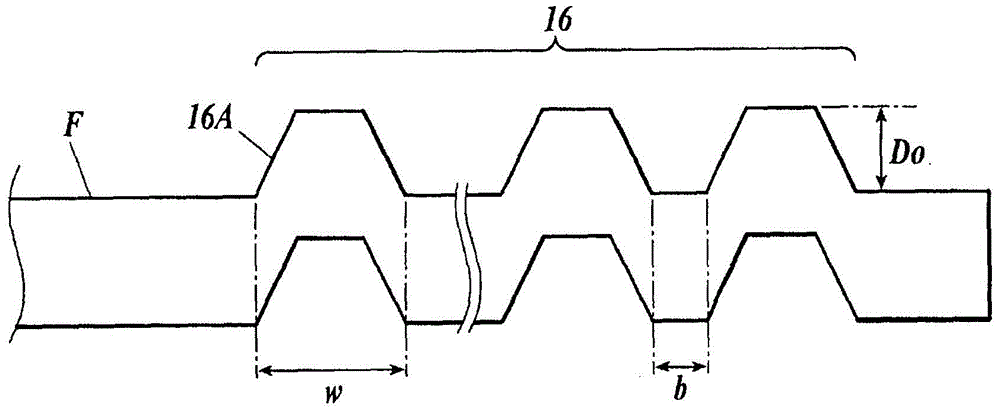
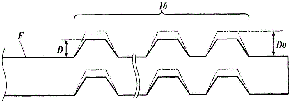
Optical film roll, method for producing same, polarizing plate, and display device
A manufacturing method and optical film technology, applied in the direction of polarizing elements, can solve the problems of difficulty in obtaining sufficient effects, fluctuations in embossing height, and differences in length directions, etc., achieve stable and uniform optical characteristics, and prevent the deterioration of the winding shape Effect
- Summary
- Abstract
- Description
- Claims
- Application Information
AI Technical Summary
Problems solved by technology
Method used
Image
Examples
Embodiment 1
[0542]
[0543] Cellulose ester 1: acetyl substitution degree (total substitution degree of acyl groups) 2.88, weight average molecular weight Mw=220000, number average molecular weight Mn=90000, Mw / Mn=2.4
[0544] Cellulose ester 2: acetyl group substitution degree (total substitution degree of acyl group) 2.35, weight average molecular weight Mw=215000, number average molecular weight Mn=100000, Mw / Mn=1.5
[0545] Cellulose ester 3: acetyl substitution degree 1.50, propionyl substitution degree 0.90, total acyl substitution degree 2.40, weight average molecular weight Mw=160000, number average molecular weight Mn=100000, Mw / Mn=2.2
[0546]
[0547]
[0548] 10 parts by mass of Aerosil 972V (manufactured by Japan Aerosil Co., Ltd., average diameter of primary particles: 16 nm, apparent specific gravity: 90 g / liter) and 90 parts by mass of methanol were stirred and mixed with a dissolver for 30 minutes, and then dispersed with Manton-Gaulin , to obtain a particle dispers...
Embodiment 2
[0644] In the production of the roll body 102 of the optical film of Example 1, the magnification of the pre-stretching in the width direction (TD direction) was carried out under the conditions described in Table 2, and the optical film was produced in the same manner. Volumes 201-206.
[0645] With respect to the produced roll body of the optical film, the following haze evaluation was performed in addition to the evaluation of winding deviation and display unevenness performed in Example 1.
[0646] (haze)
[0647] The obtained optical film was conditioned at 23° C.·55% RH for 5 hours or more. Next, the haze of the obtained optical film was measured with a haze meter (turbidimeter) (model: NDH 2000, manufactured by Nippon Denshoku Co., Ltd.) in accordance with JIS K-7136 under the conditions of 23° C. and 55% RH. , and evaluated using the following criteria.
[0648] 〇: Haze less than 0.5%
[0649] △: Haze 0.5% to less than 1.0%
[0650] ×: Haze is 1.0% or more
[065...
Embodiment 3
[0657] In the production of the roll body 102 of the optical film of Example 1, the average crush resistance rate (%) of the left and right embossed parts was changed by adjusting the film thickness and the temperature of the embossing roll, and the roll of the optical film described in Table 3 was produced. Body 301-306.
[0658] With respect to the roll body of each optical film, the packaging forms of the following A to C (refer to Figure 10 . ), stored in a warehouse at 30 to 40° C. and 65 to 85% RH so that the longitudinal direction of the core (rolling core) becomes horizontal for 2 months. And similarly to Example 1, the winding state of the roll after 2 months was visually observed, and the winding deviation and the optical film were extracted from the roll of each optical film, and it produced similarly to Example 1. The circular polarizing plate and the organic EL image display device were evaluated for display unevenness.
[0659] Packaging Form A: A roll body o...
PUM
| Property | Measurement | Unit |
|---|---|---|
| Film thickness | aaaaa | aaaaa |
| Roll length | aaaaa | aaaaa |
| Thickness | aaaaa | aaaaa |
Abstract
Description
Claims
Application Information
 - R&D
- Intellectual Property
- Life Sciences
- Materials
- Tech Scout
- Unparalleled Data Quality
- Higher Quality Content
- 60% Fewer Hallucinations
Browse by: Latest US Patents, China's latest patents, Technical Efficacy Thesaurus, Application Domain, Technology Topic, Popular Technical Reports.
© 2025 PatSnap. All rights reserved.Legal|Privacy policy|Modern Slavery Act Transparency Statement|Sitemap|About US| Contact US: help@patsnap.com


