Hydraulic high-frequency down-the-hole rock-breaking drill at the bottom of the rotary pile machine

A technology of rotary pile driver and hole bottom, which is applied to drill pipes, drill pipes, drilling equipment, etc., can solve the problems of only about 1 meter in 8 hours, the difficulty of drilling the drill bit into the rock quickly, and the inability to form holes at one time, so as to improve the penetration rate. The effect of rock efficiency, fast collection of crushed stone particles and high impact force

Active Publication Date: 2017-03-22
XIANGYANG CHANGKAN INTELLIGENT MACHINERY
View PDF9 Cites 0 Cited by
  • Summary
  • Abstract
  • Description
  • Claims
  • Application Information

AI Technical Summary

Problems solved by technology

[0002] For the various types of rotary pile excavators currently in use, once they encounter rock formations during the digging process, the original drill bits are difficult to enter the rock quickly. , its rock-penetrating speed is only about 1 meter in 8 hours
Although the hydraulic high-frequency percussion drill at the bottom of the rotary pile machine can impact the rock formation, no matter what kind of hydraulic percussion drill is used, it is impossible to form a hole at one time. It is necessary to replace the drill bucket to expand the hole and collect gravel, and the rock penetration speed is slow

Method used


Image

  • Hydraulic high-frequency down-the-hole rock-breaking drill at the bottom of the rotary pile machine
  • Hydraulic high-frequency down-the-hole rock-breaking drill at the bottom of the rotary pile machine
  • Hydraulic high-frequency down-the-hole rock-breaking drill at the bottom of the rotary pile machine

Examples


Embodiment Construction

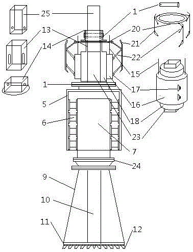
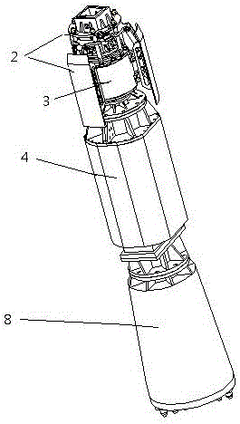
[0015] Such as figure 1 , 2 As shown, the upper end of the hydraulic down-the-hole rock-breaking drill of the present invention is provided with a detent mechanism 2 for controlling the rotary joint assembly 3, and the detent mechanism 2 is arranged on the outside of the rotary joint assembly 3. During operation, the rotary joint assembly 3 of the present invention passes through the The anti-rotation mechanism 2 is connected to the telescopic drill pipe 25 of the rotary pile excavator, and the telescopic drill pipe 25 is connected to the connection square sleeve 13 of the anti-rotation mechanism 2 through the pivot pin 19; the connection square sleeve 13 of the anti-rotation mechanism 2 is welded on the rotary joint The upper end of the central shaft 23 of the assembly 3; the rotary joint assembly 3 is composed of the rotary joint casing 16, the central shaft 23 arranged in the rotary joint casing 16, and the rotary joint mandrel 18, and the rotary joint mandrel 18 is arrange...


PUM


Abstract

The invention provides a hydraulic high-frequency DTH (down-the-hole) rock-breaking drill for a rotary pile drill hole bottom, relates to a rock breaking device on a rotary pile drill, and mainly solves the problems that one-step pore forming cannot be realized no matter what kind of a hydraulic pressure percussion drill is used for drilling by the rotary pile drill, a drilling bucket is required to be replaced for pore broadening, and stone ballast needs to be collected. A swivel joint assembly of the hydraulic high-frequency DTH rock-breaking drill for the rotary pile drill hole bottom is connected to a retractable drill rod through a rotation stopping mechanism; a central shaft of the swivel joint assembly is connected to a vibratory hammer outer cover at the lower end of the swivel joint assembly through an upper flange; the vibratory hammer outer cover is connected with vibratory hammers in the middle of the vibratory hammer outer cover through shock-absorbing blocks; the vibratory hammers are connected with a drilling bucket assembly at the lower ends of the vibratory hammers through lower flanges; 11-16 drill bits are fixed to the lower end of the drilling bucket assembly. The hydraulic high-frequency DTH rock-breaking drill is large in impulsive force, and high in pore-forming speed; broken stone particles can be collected while the vibratory hammer vibrates for impact, and the effect that the rotary pile drill utilizes a common drilling bucket to construct at the soil layer is realized; the hydraulic high-frequency down-the-hole rock-breaking drill is good in rotation stopping effect, and high in response speed.

Description

technical field [0001] The invention relates to a rotary pile driver, in particular to a hydraulic high-frequency down-the-hole rock-breaking drill capable of drilling rock at the bottom of a rotary pile hole. Background technique [0002] For the various types of rotary pile excavators currently in use, once they encounter rock formations during the digging process, the original drill bits are difficult to enter the rock quickly. At this time, its rock-penetrating speed is only about 1 meter in 8 hours. Although the hydraulic high-frequency percussion drill at the bottom of the rotary pile machine can impact the rock formation, no matter what kind of hydraulic percussion drill is used, it is impossible to form a hole at one time. It is necessary to replace the drill bucket to expand the hole and collect gravel, and the rock penetration speed is relatively slow. Therefore, the problem of rapid rock penetration at the bottom of the hole of the rotary pile machine has always ...

Claims


Application Information

Patent Timeline
Patent Type & Authority Patents(China)
IPC IPC(8): E21B4/16E21B17/02
CPCE21B4/16E21B17/07
Inventor 邵波
Owner XIANGYANG CHANGKAN INTELLIGENT MACHINERY
Why Eureka
Try Eureka