
Remote switch device control system with load detection

A remote switch and equipment control technology, applied in the general control system, control/regulation system, program control, etc., can solve the problems of lack of ability to monitor the operating status of the controlled equipment, unable to detect the operating status of fans, lights, and complicated operations. To achieve the effect of convenient networking mode, lower installation cost, and lower complexity

Inactive Publication Date: 2015-08-19
STATE GRID CORP OF CHINA +3
View PDF6 Cites 5 Cited by
  • Summary
  • Abstract
  • Description
  • Claims
  • Application Information

AI Technical Summary

Problems solved by technology

However, the power environment host lacks the ability to monitor the operating status of the controlled equipment
For example, the power environment host can be used to open the load circuit of the corresponding fan and light, but the power environment host cannot detect the operating status of the fan and light (such as whether the light bulb is broken, whether the fan is broken or overloaded, etc.); The method is to check the video of the controlled equipment through the remote video monitoring system to identify the working status of the controlled equipment. This method is inefficient and complicated to operate.

Method used


Image

  • Remote switch device control system with load detection

Examples


Embodiment Construction

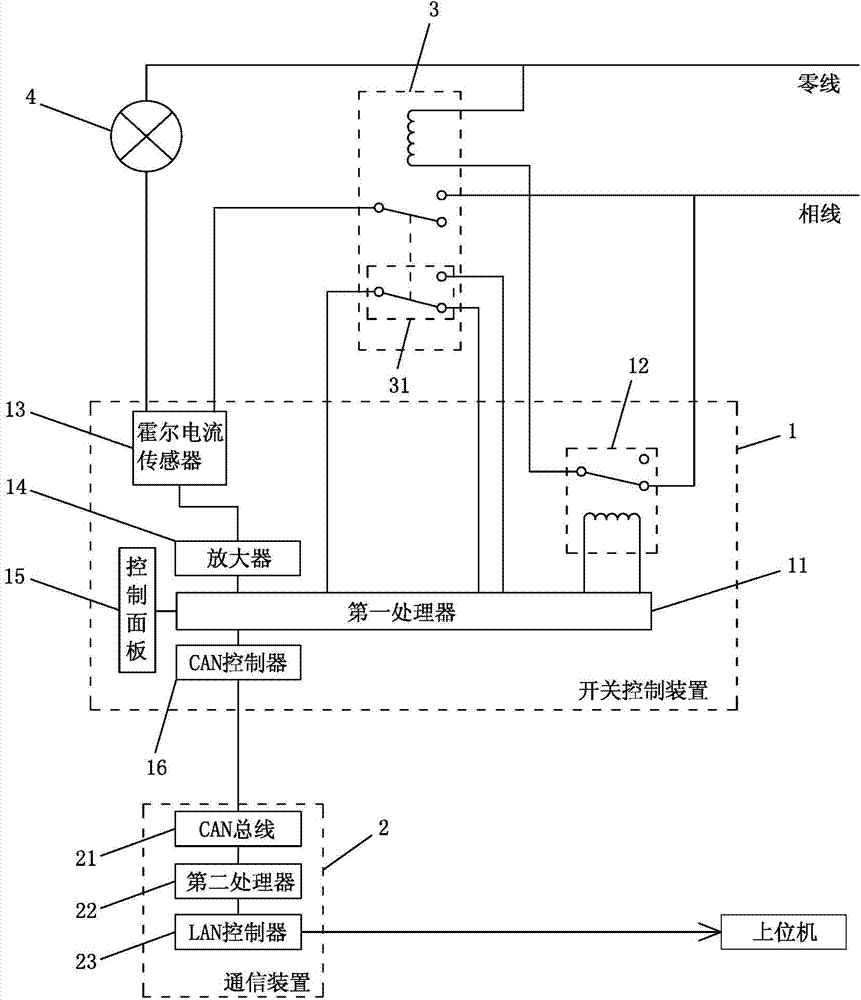
[0015] refer to figure 1 As shown, a remote switchgear control system with load detection includes an AC contactor 3 for controlling the on-off of the load circuit, a switch control device 1 and a communication device 2, wherein the load circuit includes a connection between the neutral line and the phase line Between the load 4, the AC contactor 3 is connected between the neutral line and the phase line.

[0016] The switch control device 1 comprises a first processor 11, a Hall current sensor 13, an amplifier 14, a relay 12, a CAN controller 16 and a control panel 15, and the first processor 11 communicates with the amplifier 14, the control panel 15, the relay 12 and the CAN controller respectively. The controller 16 is connected, and the Hall current sensor 13 is arranged on the load circuit, and its output terminal is connected with the amplifier 14 for measuring the current of the load circuit, and after being amplified by the amplifier 14, it is fed back to the first pr...


PUM


Abstract

The invention provides a remote switch device control system with load detection, and the system is used for remote control and load circuit detection. The system comprises a contact for controlling the on and off of a load circuit, a switch control device and a communication device. The switch control device comprises a first processor, a Hall current sensor arranged on the load circuit, an amplifier which is connected between the Hall current sensor and the first processor, and a relay which is connected to the first processor and is used for controlling the on and off of the contactor. The remote communication between the switch control device and a host computer is realized through the communication device. The load circuit is provided with the Hall current sensor and is used for measuring the current of the load circuit and sending the current to the host computer so as to judge the working state of a load device, and thus the remote monitoring of a load working state is realized.

Description

technical field [0001] The invention relates to a remote control system. Background technique [0002] In places such as substations and switching stations, due to the requirements of remote management, it is necessary to carry out remote start and stop control of lights, fans and other equipment. At present, there are corresponding power environment monitoring hosts that can realize corresponding functions. However, the power environment host lacks the ability to monitor the operating status of the controlled equipment. For example, the power environment host can be used to open the load circuit of the corresponding fan and light, but the power environment host cannot detect the operating status of the fan and light (such as whether the light bulb is broken, whether the fan is broken or overloaded, etc.); The method is to check the video of the controlled equipment through the remote video monitoring system to identify the working status of the controlled equipment. This ...

Claims


Application Information

Patent Timeline
Patent Type & Authority Applications(China)
IPC IPC(8): G05B19/418
CPCY02P90/02G05B19/41885
Inventor 王铮黄初指吴玉蓉杨辉龙黄灿锋
Owner STATE GRID CORP OF CHINA
Learn More