
Energy storage system collocation method and system

An energy storage system and particle swarm algorithm technology, applied in the energy storage system configuration method and system field, can solve problems such as the inability to guarantee the optimal scheduling state of the energy storage system, insufficient performance of the energy storage system, and a single optimal configuration model

Active Publication Date: 2015-07-29
STATE GRID CORP OF CHINA +1
View PDF6 Cites 13 Cited by
  • Summary
  • Abstract
  • Description
  • Claims
  • Application Information

AI Technical Summary

Problems solved by technology

[0005] The technical problem to be solved in this application is to provide an energy storage system configuration method and system, which solves the problem that the energy storage system (ESS) optimal configuration model established in the prior art is relatively single, and the effect on the energy storage system is not fully reflected. The optimal configuration results obtained cannot guarantee that the energy storage system of each configuration is in the optimal scheduling state during operation.

Method used


Image

  • Energy storage system collocation method and system
  • Energy storage system collocation method and system
  • Energy storage system collocation method and system

Examples


Embodiment Construction

[0058] The following will clearly and completely describe the technical solutions in the embodiments of the application with reference to the drawings in the embodiments of the application. Apparently, the described embodiments are only some of the embodiments of the application, not all of them. Based on the embodiments in this application, all other embodiments obtained by persons of ordinary skill in the art without making creative efforts belong to the scope of protection of this application.

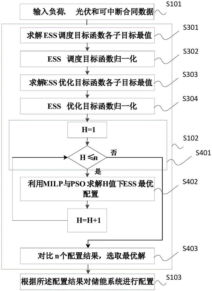
[0059] refer to figure 1 , which shows a flow chart of an embodiment of an energy storage system configuration method in the present application, which may include the following steps:

[0060] Step S101: Obtain target data.

[0061] In this application, the target data includes annual load data, photovoltaic power generation output data and interruptible load contract data.

[0062] Step S102: Using the mixed integer linear programming method and the particle swarm optimization a...


PUM


Abstract

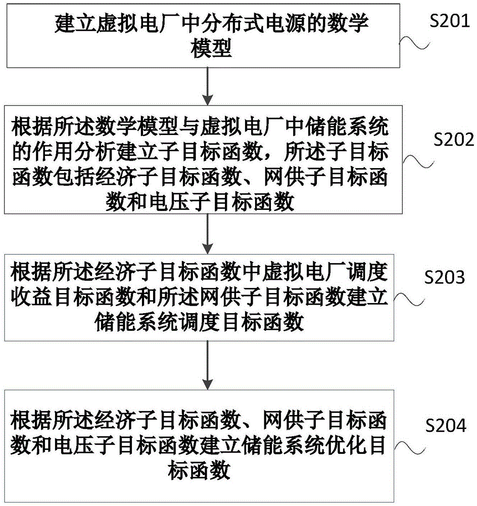
The invention provides an energy storage system collocation method, which comprises the steps: obtaining target data; utilizing a mixed integral linear programming method and a particle swarm optimization to respectively calculate an energy storage system scheduling objective function and an energy storage system optimizing objective function; utilizing an energy storage system optimizing collocation result to collocate an energy storage system, wherein the building processes of the energy storage system scheduling objective function and the energy storage system optimizing objective function comprise the steps: a distributed generation mathematic model in a virtual power plant is built; a sub-objective function is analyzed and built according to the mathematic model and the effect of the energy storage system in the virtual power plant and comprises an economy sub-objective function, a network supply sub-objective function and a voltage sub-objective function; the energy storage system scheduling objective function and the energy storage system optimizing objective function are respectively built according to the sub-objective functions. According to an optimizing collocation result solved by an energy storage system optimizing collocation model, the energy storage system of each collocation can be in an optimal scheduling state during operation and work.

Description

technical field [0001] The present application relates to the field of electric power, and in particular to an energy storage system configuration method and system. Background technique [0002] With the development of technology, people have higher and higher requirements for energy storage system configuration. [0003] The existing large-scale photovoltaic energy storage system configuration method obtains the charging and discharging control strategy of the energy storage system by using the first-order low-pass filter algorithm to process the photovoltaic output power, and takes the annual average minimum cost as the objective function to establish the energy storage system The (ESS) optimal configuration model is relatively simple, and it does not fully reflect the role of the energy storage system. The optimal configuration results obtained cannot guarantee that each configuration of the energy storage system is in the optimal scheduling state during operation. [0...

Claims


Application Information

Patent Timeline
Patent Type & Authority Applications(China)
IPC IPC(8): G06Q10/04G06Q50/06
CPCY02E40/70Y04S10/50
Inventor 赵波韦立坤张雪松周丹吴红斌
Owner STATE GRID CORP OF CHINA
Learn More