The Elastic Manipulation Structure of the Upturn Door of Furniture
A technology for manipulating structures and furniture, applied in door/window fittings, hinges with pins, building structures, etc., can solve the problems of inability to meet the needs of use, inability to achieve uniformity, and large friction, and achieve small collisions and accurate positioning. And stable, the effect of eliminating contact noise
- Summary
- Abstract
- Description
- Claims
- Application Information
AI Technical Summary
Problems solved by technology
Method used
Image
Examples
no. 1 example
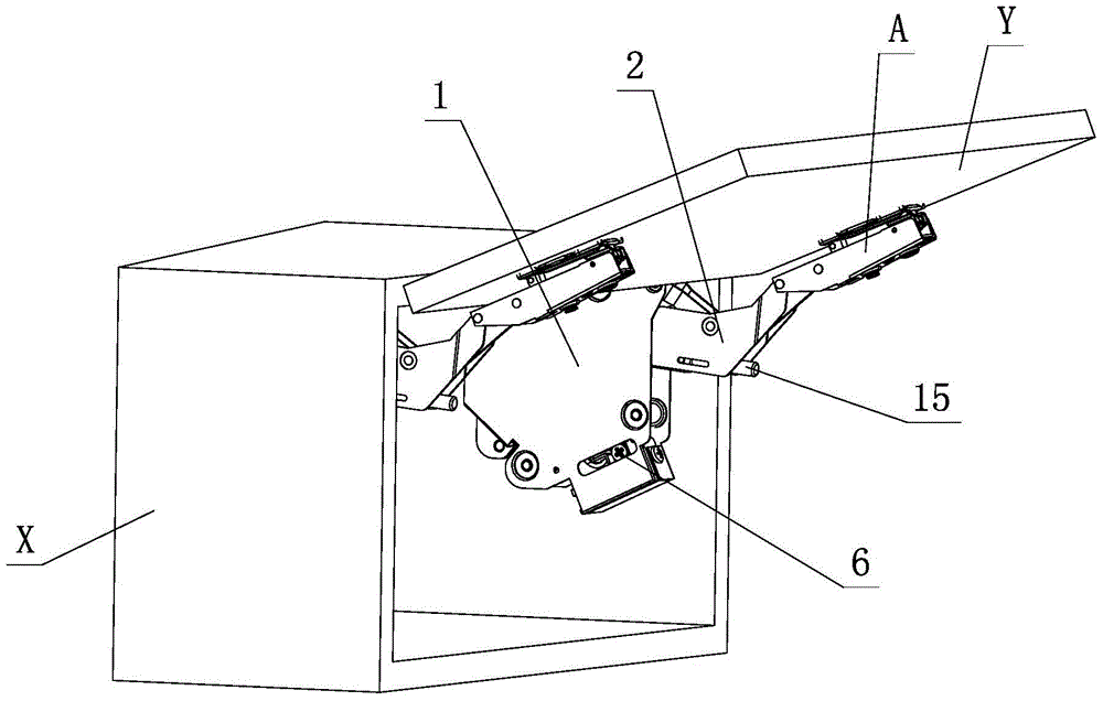
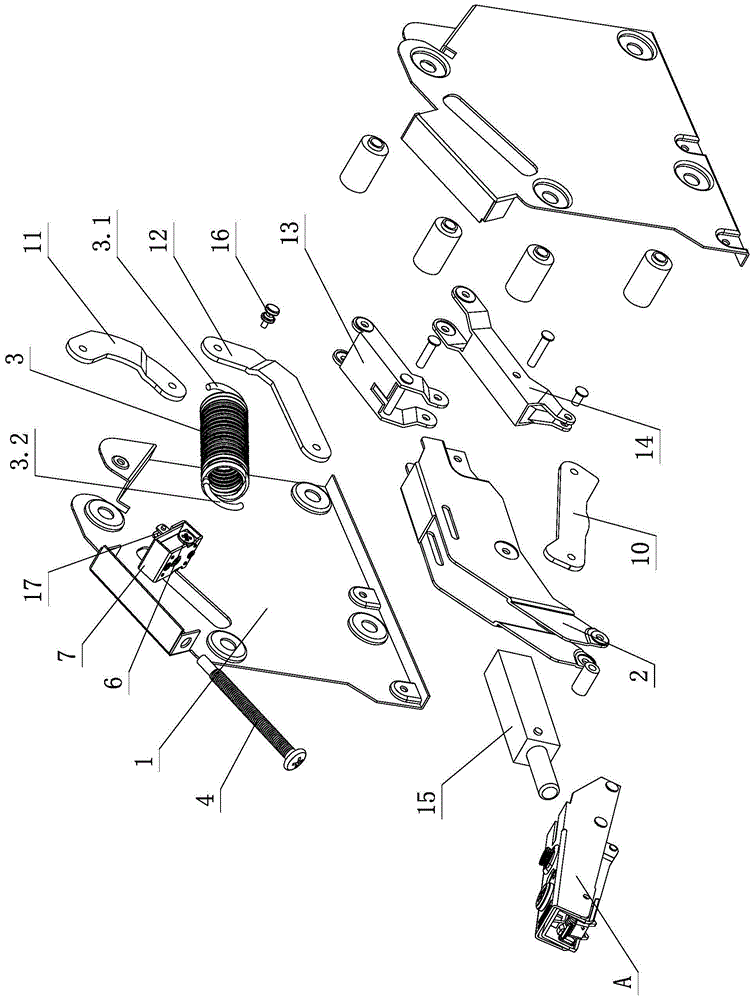
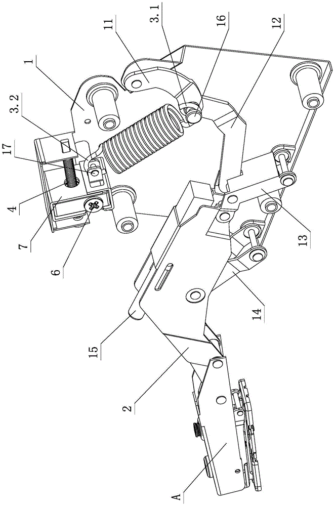
[0025] see Figure 1-Figure 6 , the elastic force control structure of the furniture upturning door, including the upturning device, the upturning device includes a fixed seat 1, a hinged arm 2, a spring 3, a connecting arm assembly, and is arranged on the fixed seat 1, and is used to adjust the upturning device. The adjustment assembly of the opening and closing force, the connecting arm assembly at least includes a first connecting arm 11 and a second connecting arm 12, one end of the first connecting arm 11 is hinged with the fixed seat 1, the other end is hinged with one end of the second connecting arm 12, and the second connecting arm 11 is hinged at one end. The other end of the connecting arm 12 is hinged with the fixed seat 1 and / or the hinged arm 2; the first connecting arm 11 and the second connecting arm 12 are hinged through the first pin shaft 16, and the first pin shaft 16 is provided with a groove 16.1, One end of the spring 3 acts on the groove 16.1, and the o...
no. 2 example
[0034] see Figure 7 , Figure 8 , the elastic operating structure of the furniture’s upper flap door, the first pin shaft 16 is provided with hinged parts 16.2 on both sides, and the first connecting arm 11 and the second connecting arm 12 are connected through the hinged part 16.2, the first connecting arm 11 and The second connecting arm 12 is hinged to each other through the hinge part 16.2; a step 16.3 is formed between the groove 16.1 and the hinge part 16.2, and the first pull hook 3.1 is limited to rotate on the groove 16.1 and is connected to the first through the step 16.3. The arm 11 and the second connecting arm 12 are spaced apart and placed between the first connecting arm 11 and the second connecting arm 12 .
[0035] Others are not described with the first embodiment.
PUM
 Abstract
Description
Claims
Application Information
 - R&D
- Intellectual Property
- Life Sciences
- Materials
- Tech Scout
- Unparalleled Data Quality
- Higher Quality Content
- 60% Fewer Hallucinations
Browse by: Latest US Patents, China's latest patents, Technical Efficacy Thesaurus, Application Domain, Technology Topic, Popular Technical Reports.
© 2025 PatSnap. All rights reserved.Legal|Privacy policy|Modern Slavery Act Transparency Statement|Sitemap|About US| Contact US: help@patsnap.com


