Opening and closing force adjustment mechanism for furniture upturning doors
A technology for adjusting mechanism and opening and closing force, which is applied in door/window fittings, building structures, and switches with braking devices, etc. The force cannot be adjusted when moving or opening the movement, etc., to achieve the effect of quick adjustment, wide range of use, and simple and reasonable structure
- Summary
- Abstract
- Description
- Claims
- Application Information
AI Technical Summary
Problems solved by technology
Method used
Image
Examples
no. 1 example
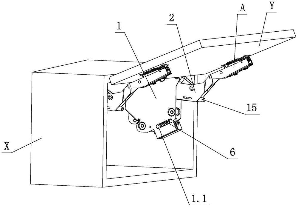
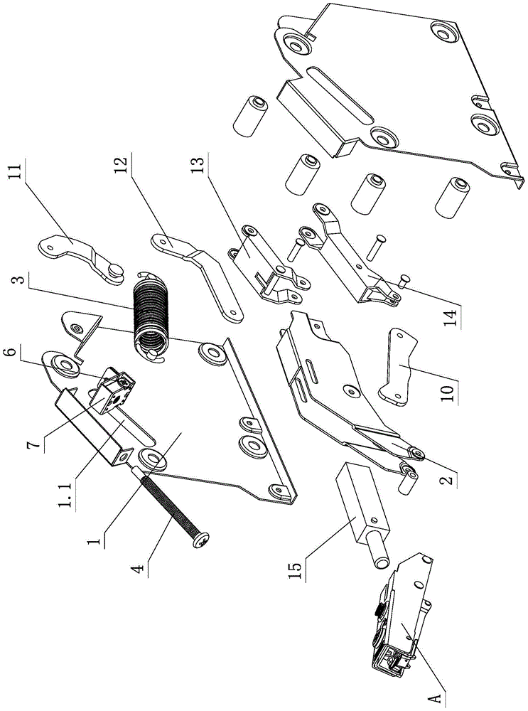
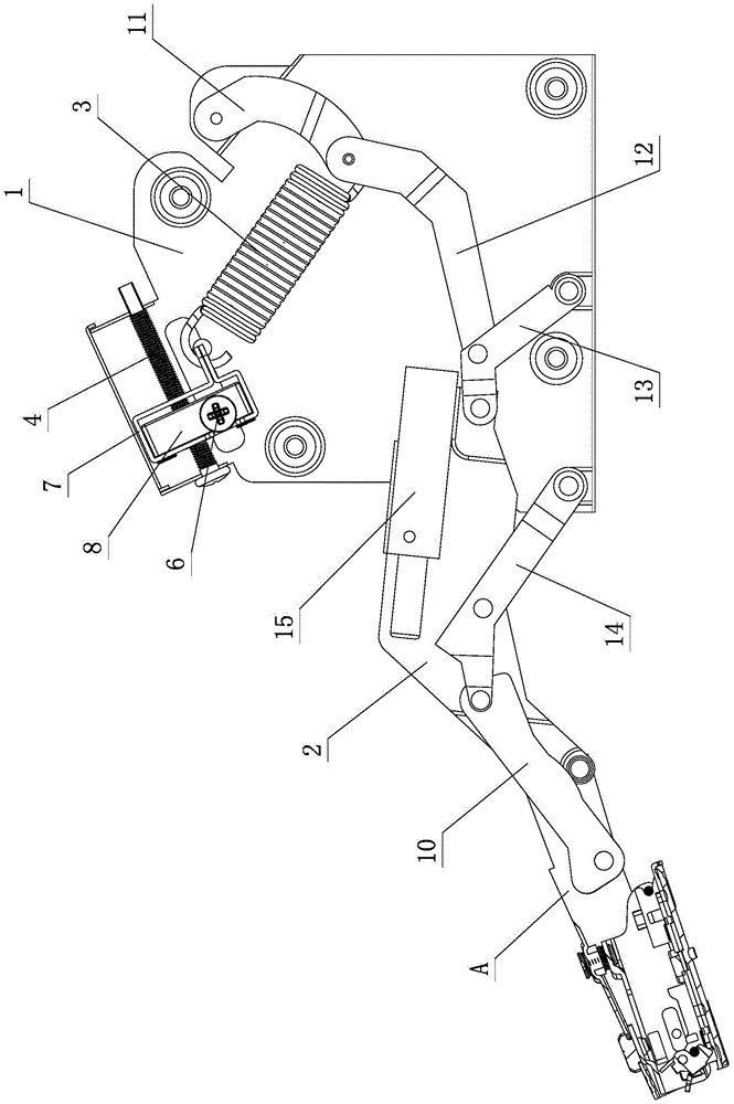
[0023] see Figure 1-Figure 4 , the opening and closing force adjustment mechanism used for furniture upturning doors, including upturning devices and lock-off devices A that are respectively arranged on the furniture cabinet body X and furniture upturning doors Y; wherein, the upturning devices include fixing seats 1, Articulated arm 2, spring 3 and connecting arm assembly, one end of the connecting arm assembly is connected to the articulated arm 2, and the other end is connected to the fixed seat 1, one end of the spring 3 acts on the connecting arm assembly, and the other end acts on the fixed seat 1, and the fixed seat 1 and / or the connecting arm assembly is provided with an adjustment assembly for adjusting the opening and closing force of the turning device. The adjustment assembly includes a screw rod 4, a transmission tooth 5 and a transmission rod 6; wherein, the screw rod 4 is fixedly connected with the transmission tooth 5 or rotated by a thread Connection, the two...
no. 2 example
[0032] see Figure 5 , Image 6 , which is used for the opening and closing force adjustment mechanism of the upward flap of furniture. The screw rod 4 is connected to the fixed seat 1 in positioning and rotation, and is fixedly connected to or integrally formed with the transmission tooth 5. The transmission rod 6 is connected to the fixed seat 1 in positioning and rotation, and is provided with The transmission rod threaded part 6.2 and the transmission tooth 5 are mutually engaged and driven, and the support element 7 is provided with a support element threaded part and a screw rod 4 threaded rotation connection; through the tool action part 6.1, the transmission rod 6 rotates and is driven by the transmission rod threaded part 6.2 The transmission tooth 5 and the screw rod 4, the support element 7 is connected with the screw rod 4 through the threaded part of the support element, and the front and rear linear sliding displacement can be positioned along the front and rear ...
PUM
 Abstract
Description
Claims
Application Information
 - R&D
- Intellectual Property
- Life Sciences
- Materials
- Tech Scout
- Unparalleled Data Quality
- Higher Quality Content
- 60% Fewer Hallucinations
Browse by: Latest US Patents, China's latest patents, Technical Efficacy Thesaurus, Application Domain, Technology Topic, Popular Technical Reports.
© 2025 PatSnap. All rights reserved.Legal|Privacy policy|Modern Slavery Act Transparency Statement|Sitemap|About US| Contact US: help@patsnap.com


