Attached type lifting device for cleaning tall and big-space of cleaning chamber

A high-space, clean-room technology, applied in construction, building structure, processing of building materials, etc., can solve problems such as efficiency and safety cannot be guaranteed, and achieve the effect of avoiding the danger of falling, high efficiency and improving efficiency.

Inactive Publication Date: 2015-07-29
柏诚系统科技股份有限公司
View PDF6 Cites 1 Cited by
  • Summary
  • Abstract
  • Description
  • Claims
  • Application Information

AI Technical Summary

Problems solved by technology

[0003] In order to solve the problem that the efficiency and safety of the traditional high and large space ceiling installation cannot be guaranteed, and improve the efficiency and safety of material vertical transportation, the present invention provides a clean attachment type lifting device for high and large spaces in clean rooms. In order to achieve the above objectives, the present invention adopts The following technical solutions: the present invention includes a mobile scaffold 1, a mobile material lifting device 2, and the mobile material lifting device 2 includes a mobile base 21, a moving track 25, a transport shelf 23, a hoist 22, a traction wire rope 24, and a connecting caster 28 , the connecting plate 26, the upper surface of the mobile base 21 is fixed with a moving track 25 and a hoist 22, the upper and lower top ends of the moving track 25 are fixedly connected with the mobile scaffold 1 through the movable connection device 12, and the left and right sides of the moving track 25 Connecting casters 28 are respectively provided; the connecting casters 28 are connected with the transport shelf 23 through the connecting plate 26; the traction wire rope 24 is fixed above the transport shelf 23; The output end is connected, and the fixed pulley 27 is fixed on the mobile scaffold 1

Method used


Image

  • Attached type lifting device for cleaning tall and big-space of cleaning chamber

Examples


Embodiment Construction

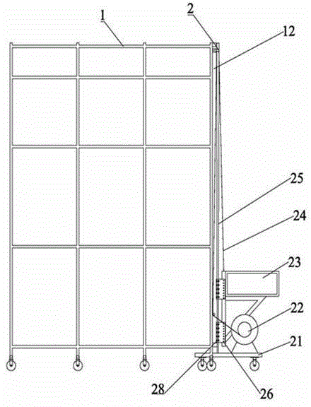
[0010] Depend on figure 1 As can be seen, the present invention includes a mobile scaffold 1, a mobile material lifting device 2, and the mobile material lifting device 2 includes a mobile base 21, a moving track 25, a transport shelf 23, a hoist 22, a traction wire rope 24, and connecting casters 28 , the connecting plate 26, the upper surface of the mobile base 21 is fixed with a moving track 25 and a hoist 22, the upper and lower top ends of the moving track 25 are fixedly connected with the mobile scaffold 1 through the movable connection device 12, and the left and right sides of the moving track 25 Connecting casters 28 are respectively provided; the connecting casters 28 are connected with the transport shelf 23 through the connecting plate 26; the traction wire rope 24 is fixed above the transport shelf 23; The output end is connected, and the fixed pulley 27 is fixed on the mobile scaffold 1.

[0011] Preferably, at least three pairs of connecting casters 28 are fixe...


PUM


Abstract

The invention discloses an attached type lifting device for cleaning a tall and big-space of a cleaning chamber. The device comprises a movable scaffolding and a movable material lifting device, wherein the movable material lifting device comprises a mobile base, a mobile rail, a conveying goods shelf, a winch, a dragging steel cable, connecting trundles and a connecting plate, wherein the mobile rail and the winch are fixed on the upper surface of the mobile base; the upper and lower top ends of the mobile rail are fixedly connected with the movable scaffolding by movable connecting devices; the connecting trundles are respectively arranged on the left and right sides of the mobile rail; the connecting trundles are connected with the conveying goods shelf by the connecting plate; the dragging steel cable is fixed above the conveying goods shelf; the other end of the dragging steel cable is connected with a power output end of the winch by being wound on a fixed pulley; the conveying goods shelf is lifted up and down along the mobile rail by the connecting trundles under the lifting of the dragging steel cable; during lifting, materials do not fall off, the lifting operation is finished on the ground, the lifting device is quite simple and convenient to mount and dismount, safe and quite high in efficiency.

Description

technical field [0001] The invention relates to the installation of FFU and suspended ceiling structure in a clean room, in particular to a clean attachment type lifting device for tall and large spaces in a clean room. Background technique [0002] At present, the FFU ceiling in the clean room of the domestic large-scale and high-structure electronic factory building, the installation of the FFU ceiling structure usually uses mobile scaffolding and self-propelled lifts to hang the steel structure, keel, FFU and blind plate installation, this method is suitable for large areas, large spaces and high heights In plant engineering, there are shortcomings such as low efficiency and poor safety during use. The main reason is that there is no efficient and reliable method for vertical transportation of materials. Contents of the invention [0003] In order to solve the problem that the efficiency and safety of the traditional high and large space ceiling installation cannot be g...

Claims


Application Information

Patent Timeline
IPC IPC(8): E04G21/16
Inventor 李铀龚成高隽臣
Owner 柏诚系统科技股份有限公司
Why Eureka
Try Eureka