
Detection device for circuit breakage and short circuit of secondary coil of electric leakage mutual inductor

A detection device and secondary coil technology, applied in circuit breaker testing, measuring devices, instruments, etc., can solve problems such as large current, reduced system reliability and ease of production, increased system cost and complexity, etc.

Inactive Publication Date: 2015-07-22
上海盛善电气有限公司
View PDF8 Cites 7 Cited by
  • Summary
  • Abstract
  • Description
  • Claims
  • Application Information

AI Technical Summary

Problems solved by technology

Although the former method can detect broken wires, when the rated current of the leakage transformer is very large, when it is desired to detect a reliable current for the second time, the artificially applied current is very large, which increases the cost and complexity of the system ; The latter method needs to add a load disconnection detection current module in the secondary coil circuit. Although the cost of the system is reduced to a certain extent, it does not reduce the complexity of the entire system. The additional load disconnection detection current module also means Significantly reduces the reliability and ease of production of the entire system
Moreover, the above two methods can only detect whether the leakage transformer is in a disconnected state, and cannot accurately detect whether the leakage transformer is in a short circuit state, and there is no way to measure the external residual current value while detecting the current state of the leakage transformer

Method used


Image

  • Detection device for circuit breakage and short circuit of secondary coil of electric leakage mutual inductor
  • Detection device for circuit breakage and short circuit of secondary coil of electric leakage mutual inductor

Examples


Embodiment 1

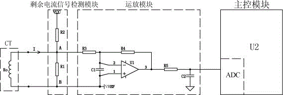
[0032]VREF=2.5V, VCC=5V, R1=100Ω, R1’=25Ω, R2=300Ω, R3=10K, R4=40K. When the secondary coil of the leakage transformer is disconnected, the DC voltage Vdc1=VREF-(VCC-VREF)*R1 / (R1+R2)*(R4 / R3)=0V; when the secondary coil of the leakage transformer is short-circuited, the DC voltage Vdc2 = VREF = 2.5V;

[0033] When the leakage transformer secondary coil is in normal state, DC voltage Vdc3=VREF-(VCC-VREF)*R1' / (R1'+R2)*(R4 / R3)=1.73V; AC voltage Vac3=(I* R1)*(R4 / R3)=400I, that is, I=Vac3 / 400.

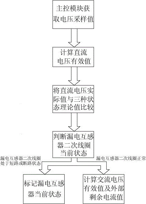
[0034] The main control module can judge the current state of the secondary coil of the leakage transformer according to the magnitude of the DC voltage value measured when the secondary coil of the leakage transformer is in different states, and then consider the measurement error factor of an appropriate size. In Embodiment 1, the criterion of the main control module is: when the DC voltage value is within the range of 0V-0.1V, the secondary coil of the leakage transformer is in an open ...

Embodiment 2

[0036] VREF=2.5V, VCC=5V, R1=100Ω, R1’=25Ω, R2=300Ω, R3=10K, R4=20K. When the secondary coil of the leakage transformer is disconnected, the DC voltage Vdc1=VREF-(VCC-VREF)*R1 / (R1+R2)*(R4 / R3)=1.25V; when the secondary coil of the leakage transformer is short-circuited, the DC Voltage Vdc2 = VREF = 2.5V;

[0037] When the leakage transformer secondary coil is in normal state, DC voltage Vdc3=VREF-(VCC-VREF)*R1' / (R1'+R2)*(R4 / R3)=2.12V; AC voltage Vac3=(I* R1)*(R4 / R3)=200I, that is, I=Vac3 / 200.

[0038] The main control module can judge the current state of the secondary coil of the leakage transformer according to the magnitude of the DC voltage value measured when the secondary coil of the leakage transformer is in different states, and then consider the measurement error factor of an appropriate size. In Embodiment 2, the criterion of the main control module is: when the DC voltage value is in the range of 1.15V-1.35V, the secondary coil of the leakage transformer is in an o...

Embodiment 3

[0040] VREF=2.5V, VCC=5V, R1=100Ω, R1’=25Ω, R2=200Ω, R3=10K, R4=20K. When the secondary coil of the leakage transformer is disconnected, the DC voltage Vdc1=VREF-(VCC-VREF)*R1 / (R1+R2)*(R4 / R3)=0.83V; when the secondary coil of the leakage transformer is short-circuited, the DC Voltage Vdc2 = VREF = 2.5V;

[0041] When the leakage transformer secondary coil is in normal state, DC voltage Vdc3=VREF-(VCC-VREF)*R1' / (R1'+R2)*(R4 / R3)=1.94V; AC voltage Vac3=(I* R1)*(R4 / R3)=200I, that is, I=Vac3 / 200.

[0042] The main control module can judge the current state of the secondary coil of the leakage transformer according to the magnitude of the DC voltage value measured when the secondary coil of the leakage transformer is in different states, and then consider the measurement error factor of an appropriate size. In Embodiment 3, the criterion of the main control module is: when the DC voltage value is in the range of 0.73V-0.93V, the secondary coil of the leakage transformer is in an o...


PUM


Abstract

The invention discloses a detection device for circuit breakage and short circuit of a secondary coil of an electric leakage mutual inductor. The detection device comprises a residual current signal detection module, an operational amplifier module and a main control module, wherein the residual current signal detection module is used for detecting the operational amplifier module; the operational amplifier module is connected with the main control module; a sampling resistor in the residual current signal detection module is adopted to sample a present value of a direct-current voltage component according to the Ohm's law; the operational amplifier module is used for amplifying the direct-current voltage component; the main control module is used for judging the present state of the secondary coil of the leaking mutual inductor by calculating the amplified value of the direct-current voltage component; the sampling resistor in the residual current signal detection module is used for converting present alternative-current of the leaking mutual inductor into an alternative-current voltage component; the operational amplifier module is used for amplifying the alternative-current component; the main control module is used for calculating an external residual current value according to the alternative-current component and the resistance of the sampling resistor R1. By adopting the detection device, the circuit breakage and short circuit faults of the secondary coil of the leaking mutual inductor can be easily and effectively detected, and the external residual current value can be normally measured.

Description

technical field [0001] The invention relates to the technical field of detection of electrical fire monitoring systems, in particular to a detection device for open circuit and short circuit of a leakage transformer secondary coil. Background technique [0002] Leakage transformers are important components in power systems. When the leakage transformer is disconnected, a high induced voltage will be generated, which will cause damage to equipment and people. Therefore, it is often necessary to detect the disconnection of the leakage transformer in time so that the relay protection equipment can take protective measures. There are two commonly used disconnection detection methods for the leakage detection of the secondary coil of the leakage transformer: one is to add an additional detection loop to the primary loop of the leakage transformer, and the loop passes through the induction coil of the leakage transformer. Artificially applying a current change will cause an indu...

Claims


Application Information

Patent Timeline
IPC IPC(8): G01R31/06G01R31/327
Inventor 夏晓东刘晔曹科曾新民陶志明
Owner 上海盛善电气有限公司
Learn More