
Submersible linear motor and rotor thereof

A technology of linear motors and movers, applied in the direction of electric components, electromechanical devices, electrical components, etc., can solve problems such as lack of replenishment of lubricating oil, failure to form a protective oil film, wear of stators of submersible linear motors, etc., to improve the use of Lifespan, friction-relieving effect

Active Publication Date: 2015-07-15
HANS LASER TECH IND GRP CO LTD +1
View PDF4 Cites 5 Cited by
  • Summary
  • Abstract
  • Description
  • Claims
  • Application Information

AI Technical Summary

Problems solved by technology

When the inner cavity of the stator is filled with lubricating oil, due to the eccentricity of the mover, the lubricating oil on the friction surface will always be pressed out. The wear of the motor stator and mover affects the service life of the submersible linear motor

Method used


Image

  • Submersible linear motor and rotor thereof
  • Submersible linear motor and rotor thereof
  • Submersible linear motor and rotor thereof

Examples


Embodiment 1

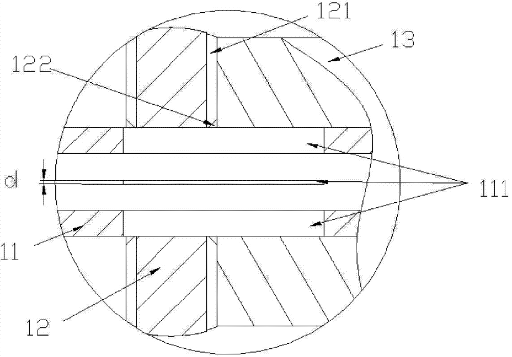
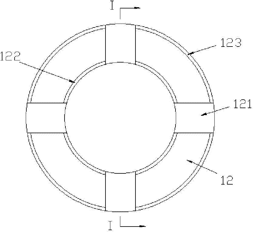
[0023] Such as Figure 1-3 As shown, the mover of the submersible linear motor in this embodiment includes the mover inner tube 11, the wear-resistant magnetic conducting ring 12 and the magnet 13 that are sleeved on the mover inner tube 11 at intervals, and the mover inner tube 11 is Hollow structure, and an oil passage 111 is provided on the pipe wall; an oil guide groove 121 is opened on the end surface of the wear-resistant magnetic conducting ring 12, and the oil passage 111 and the oil guide groove 121 are in communication with each other. By setting the oil passage 111 on the tube wall of the inner tube 11 of the mover, an oil guide groove 121 is set on the end surface of the wear-resistant magnetic permeable ring 12, and the oil passage 111 and the oil guide groove 121 are connected to each other, so that it can be connected with the inner surface of the stator. The lumen of the tube forms a circulating lubricating oil circuit. When the mover of the submersible linear ...

Embodiment 2

[0027] Such as figure 1 , 2 , 3, and 5, the submersible linear motor of this embodiment includes a stator 2, a mover 1 sleeved in the stator 2, and seals 3 arranged at both ends of the stator 2. The stator 2 includes a stator inner tube 21 and a stator coil 22 sleeved on the stator inner tube 21; the mover 1 includes a mover inner tube 11, and wear-resistant and magnetically conductive coils sleeved on the mover inner tube 11 at intervals. Ring 12 and magnet 13, the inner tube 11 of the mover is a hollow structure, and an oil passage 111 is provided on the pipe wall; an oil guide groove 121 is opened on the end surface of the wear-resistant magnetic conducting ring 12, and the oil passage 111 communicates with the oil guiding groove 121 . By setting the oil passage 111 on the tube wall of the inner tube 11 of the mover, an oil guide groove 121 is set on the end surface of the wear-resistant magnetic permeable ring 12, and the oil passage 111 and the oil guide groove 121 are ...


PUM

PropertyMeasurementUnit
Widthaaaaaaaaaa
Gap widthaaaaaaaaaa

Abstract

The invention relates to the field of submersible linear motors, in particular to a submersible linear motor and a rotor thereof. The rotor of the submersible linear motor comprises a rotor inner pipe, wear-resistant magnetic conduction rings and magnets, wherein the wear-resistant magnetic conduction rings and the magnets are arranged on the rotor inner pipe at intervals. The rotor inner pipe is of a hollow structure. Oil passing passageways are arranged on the pipe wall. Oil guide grooves are formed in the end faces of the wear-resistant magnetic conduction rings. The oil passing passageways and the oil guide grooves are communicated with each other. The oil passing passageways and the oil guide grooves are communicated with each other, and therefore a circulation lubricating oil way is formed by the oil passing passageways, the oil guide grooves and a stator inner cavity. When the submersible linear motor rotor reciprocates to work, the pressure difference is generated by the two ends of the submersible linear motor stator inner cavity, and lubricating oil can pass through the oil passing passageways of the rotor inner pipe, flows through the oil guide grooves in the end faces of the wear-resistant magnetic conduction rings and flows to the friction faces of the wear-resistant magnetic conduction rings and the stator inner cavity to form a protection oil film. By forming the protection oil film, friction between the wear-resistant magnetic conduction rings and the stator inner cavity can be effectively relieved, and therefore the service life of the submersible linear motor is easily prolonged.

Description

technical field [0001] The invention relates to the field of oil submersible linear motors, in particular to an oil submersible linear motor and a mover thereof. Background technique [0002] The stator and the mover of the submersible linear motor are in a clearance fit. Due to the existence of magnetic attraction, the mover and the stator are always in a non-concentric state. When the inner cavity of the stator is filled with lubricating oil, due to the eccentricity of the mover, the lubricating oil on the friction surface will always be pressed out. The wear of the motor stator and mover affects the service life of the submersible linear motor. Contents of the invention [0003] The technical problem to be solved by the present invention is to provide an oil submersible linear motor and a mover in view of the above-mentioned defects of the prior art, which overcomes that the lubricating oil on the friction surface cannot be replenished during the movement of the mover ...

Claims


Application Information

Patent Timeline
IPC IPC(8): H02K41/02
Inventor 陈灿李玉廷王光能洪涛高云峰
Owner HANS LASER TECH IND GRP CO LTD
Learn More