
Composite foundation frame and its construction technology for transmission towers in steep mountainous areas

A technology for transmission towers and foundation frames, which is applied in the field of electric power and can solve the problems of high foundation exposure, poor economy, and large displacement of the top of the foundation.

Active Publication Date: 2017-02-01
CENT SOUTHERN CHINA ELECTRIC POWER DESIGN INST CHINA POWER ENG CONSULTING GROUP CORP
View PDF5 Cites 0 Cited by
  • Summary
  • Abstract
  • Description
  • Claims
  • Application Information

AI Technical Summary

Problems solved by technology

[0005] In view of the disadvantages of the above-mentioned existing design methods, such as large base exposed height, large displacement at the top of the base, and poor economy, the purpose of the present invention is to provide a mother-child foundation frame and its construction technology for transmission towers in steep mountainous areas. The unique "Mother-in-Child Foundation" frame system can effectively improve the horizontal bearing capacity of the main column of the foundation, reduce the horizontal displacement of the column of the foundation, and thus reduce the amount of concrete and steel bars used in the foundation

Method used


Image

  • Composite foundation frame and its construction technology for transmission towers in steep mountainous areas
  • Composite foundation frame and its construction technology for transmission towers in steep mountainous areas
  • Composite foundation frame and its construction technology for transmission towers in steep mountainous areas

Examples


Embodiment Construction

[0058] The present invention will be further described in detail below in conjunction with the accompanying drawings and specific embodiments.

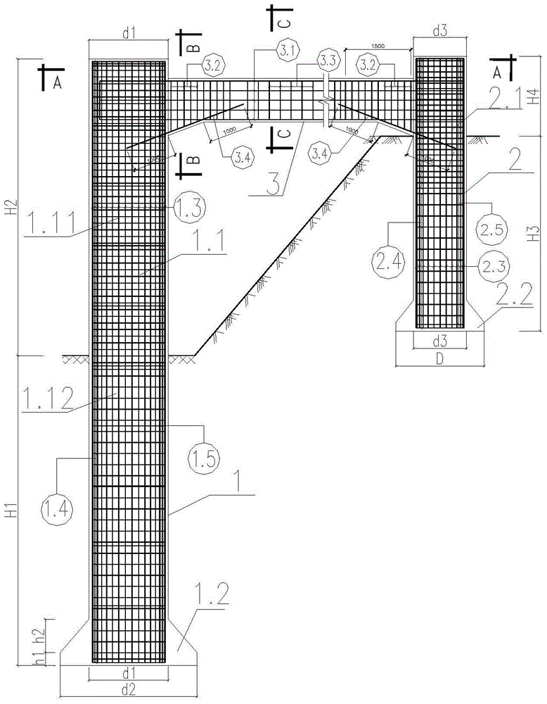
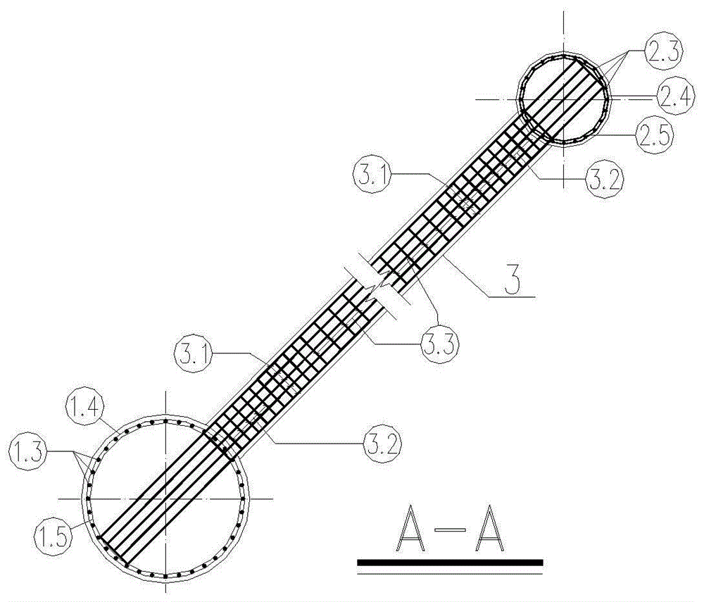
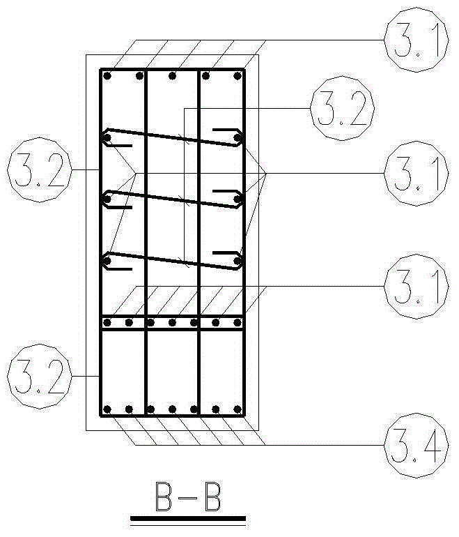
[0059] As shown in the figure, the mother-child foundation frame for transmission towers in steep mountainous areas is characterized in that it includes mother foundation 1, sub-foundation 2 and main coupling beam 3, and the two ends of main coupling beam 3 are respectively connected to mother foundation 1 and sub-foundation 2 connection, the parent foundation 1 and the sub-foundation 2 form a frame structure through the main beam 3;

[0060] The female foundation 1 includes the main column 1.1 of the female foundation and the expanded bottom 1.2 of the female foundation. The main column 1.1 of the female foundation includes the exposed height section 1.11 of the female foundation and the buried depth section 1.12 of the female foundation. The angle steel is connected with the steel truss of the upper transmission tower to directly be...


PUM


Abstract

The invention discloses a composite base framework used for a power transmission tower in a steep mountainous area. The composite base framework comprises a master base, a slave base and a main binding beam, wherein the master base comprises a master base main post and a master base expanding bottom; the master base main post comprises a master base compact exposure section and a master base embedding section; the slave base comprises a slave base main post and a slave base expanding bottom, wherein the slave base main post comprises a slave base compact exposure section and a slave base embedding section; the main binding beam is provided with a main binding beam main reinforcement, main binding beam reinforcement stirrups, a main binding beam non-reinforcement stirrup and main binding beam end part anchorage reinforcements. The invention also provides a construction technology of the composite base framework used for the power transmission tower in the steep mountainous area. The composite base frame system with the binding beam is adopted to replace a traditional means that the base main post is deepened and thickened or a multi-post bearing platform is adopted, the horizontal bearing performance of the base main post can be effectively improved, the horizontal displacement of the base main post is reduced so as to reduce the use amount of base concrete and reinforcing steel bars, and the invention performs a prominent engineering significance on environment protection, conservation of water and soil and terrain condition adaption.

Description

technical field [0001] The invention relates to the field of electric power technology, in particular to a mother-child foundation frame for transmission towers in steep mountainous areas and a construction process thereof. Background technique [0002] With the development of my country's electric power construction, transmission line corridors are becoming more and more scarce, and the conditions of the location of the transmission tower foundation of the transmission line are getting worse and worse, especially for mountainous transmission lines, the transmission tower foundation will inevitably be located on the top of the mountain or halfway up the mountain, etc. Steep terrain. The conventional design often adopts the cooperation of the all-round long and short legs of the transmission tower and the unequal height foundation, which can avoid the high slope problem caused by the construction of a large number of squares to a certain extent. [0003] However, when the tra...

Claims


Application Information

Patent Timeline
Patent Type & Authority Patents(China)
IPC IPC(8): E02D27/42E02D27/10
CPCE02D27/10E02D27/42
Inventor 曾二贤杨景胜吴海洋郭念陈一军白强王学群冯衡田三明刘林芳张荣生徐彬夏谦孙欣苗张轶冯德奎
Owner CENT SOUTHERN CHINA ELECTRIC POWER DESIGN INST CHINA POWER ENG CONSULTING GROUP CORP
Learn More