
Method and system for calibrating multiple cameras

A camera and calibration error technology, which is applied in the field of calibration of multiple cameras, can solve problems such as inaccurate object position positioning, error accumulation and propagation, and large binocular camera errors.

Active Publication Date: 2015-07-08
RICOH KK
View PDF4 Cites 22 Cited by
  • Summary
  • Abstract
  • Description
  • Claims
  • Application Information

AI Technical Summary

Problems solved by technology

Moreover, since this method adopts a sequential method to calibrate the deployed cameras, the calibration result of the binocular camera to be calibrated is related to the calibration result of the calibrated binocular camera that has an overlapping field of view with it, so there is a calibration Error Cumulative Propagation Problem
In this case, when an object to be tracked enters the field of view of the binocular camera with a large calibration error, but not in the field of view of the binocular camera with a small calibration error, it may be due to the large error of the binocular camera. Large and cause inaccurate positioning of objects

Method used


Image

  • Method and system for calibrating multiple cameras
  • Method and system for calibrating multiple cameras
  • Method and system for calibrating multiple cameras

Examples


Embodiment Construction

[0025] In order to enable those skilled in the art to better understand the present invention, the present invention will be further described in detail below in conjunction with the accompanying drawings and specific embodiments.

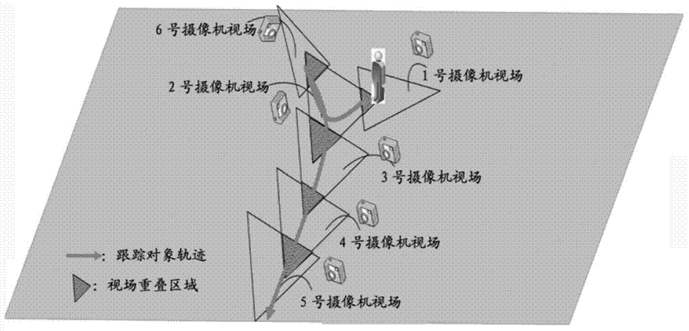
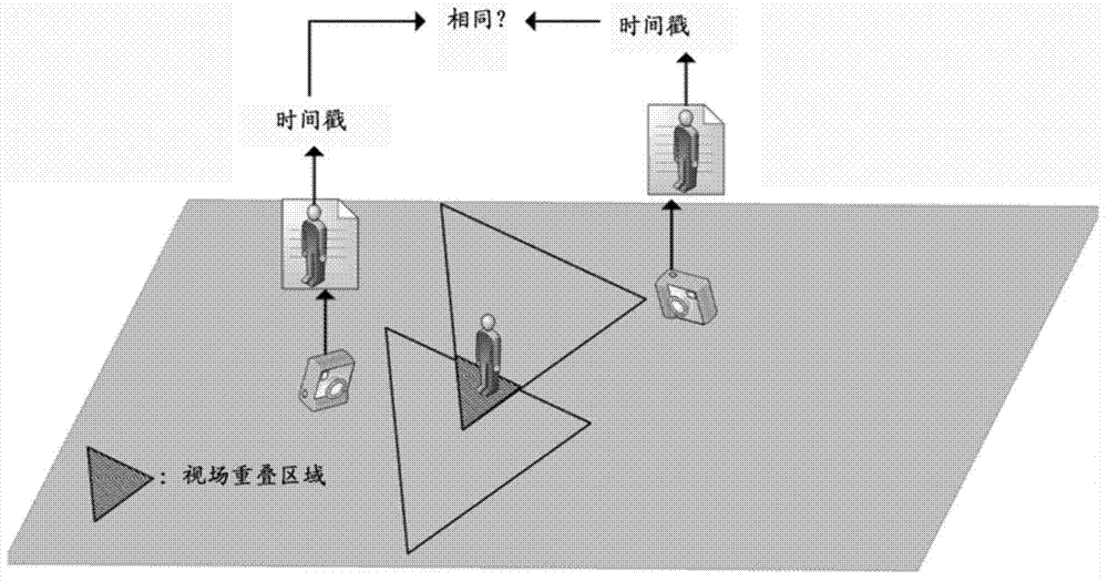
[0026] figure 1 is a schematic diagram of a site for calibrating multiple cameras according to an embodiment of the present invention. Such as figure 1 As shown, 6 binocular stereo cameras are deployed, and each binocular stereo camera is given a corresponding number. although Figure 7 6 binocular stereo cameras are given in , but the present invention can be applied to any number of binocular stereo cameras, such as 4, 5, 7, 8, 9.... figure 1 The middle triangle area represents the field of view that can be captured by each camera, and the overlapping shaded area of ​​two adjacent triangles represents the overlapping area of ​​the field of view between two different cameras. figure 2What is shown is a schematic diagram of judging the overlap...


PUM


Abstract

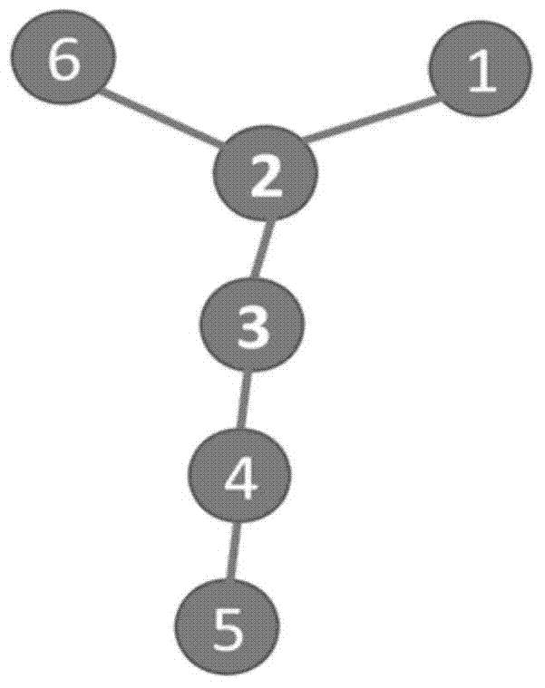
The invention provides a method for calibrating multiple cameras, comprising the following steps: synchronizing the system time of the multiple cameras; establishing a field-of-view overlap area relationship diagram of the multiple cameras; calculating the average depth error estimated value of trajectory points of a tracked object extracted from each field-of-view overlap area, estimating the calibration error magnification factor of one jump of each field-of-view overlap area based on the average depth error estimated value, and giving the corresponding jump a weight based on the estimated calibration error magnification factor so as to convert the field-of-view overlap area relationship diagram into a weighted field-of-view overlap area relationship diagram; and acquiring a reference camera corresponding to the minimum calibration cumulative error by a minimum path algorithm based on the weighted field-of-view overlap area relationship diagram.

Description

technical field [0001] The invention relates to a method and system for calibrating multiple cameras, in particular to a method and system for improving the calibration accuracy of a camera network composed of multiple cameras by dynamically selecting one or more reference cameras as reference cameras. Background technique [0002] Recently, the research on human tracking and positioning system is no longer limited to the original positioning and tracking under constrained conditions, such as in the laboratory environment, the existing research scenarios have been expanded to complex real scenes such as subway stations and airports . In addition, for the existing video surveillance system, it is required not only to accurately provide the coordinates of the tracked person in the two-dimensional image, but also to provide the position of the tracked person in the real three-dimensional space. In order to meet the above needs, a tracking system based on multiple binocular ste...

Claims


Application Information

Patent Timeline
IPC IPC(8): G06T7/00H04N17/00
Inventor 王千范圣印王鑫乔刚诸加丹
Owner RICOH KK
Learn More