Spinning machine and table holder

A spinning machine and receiving part technology, applied to spinning machines, textiles, papermaking, drafting equipment, etc., can solve the problems of large workload, spinning machine consumption, wrong setting, etc., and achieve fast and simple setting , to achieve the effect of stable placement

Inactive Publication Date: 2015-06-24
MASCHINENFABRIK RIETER AG
View PDF8 Cites 0 Cited by
  • Summary
  • Abstract
  • Description
  • Claims
  • Application Information

AI Technical Summary

Problems solved by technology

[0003] The disadvantage of pins in use is that the required deflection must be set at each spinning point and in the drafting device of the pins
This requires a large amount of work on spinning machines with several parallel drafting units
In addition, there is a risk of incorrect settings due to the different settings on different drafting units

Method used


Image

  • Spinning machine and table holder
  • Spinning machine and table holder
  • Spinning machine and table holder

Examples


Embodiment Construction

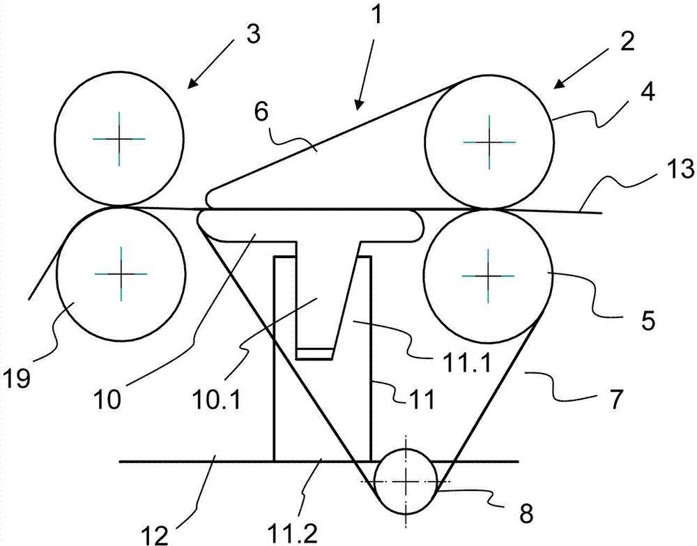
[0029] figure 1 A side view of a section of the drafting device is shown diagrammatically. Only the guide 1 with the double belt 2 and one delivery roller pair 3 is shown in this figure. The input roller pair and the oscillating support for fixing the upper roller of the drafting device are not shown here. The guiding device 1 has an upper band roll 4 and a lower band roll 5 . On the upper band roll 4 is mounted an upper band 6 which is deflected on deflection means (not shown). The lower band roll 5 is partially wound by the lower band 7 . The lower band 7 is guided by reversing rolls 8 . In addition, the lower strap 7 is wound around a guide table 10 mounted on a guide table receiver 11 . The guide table receptacle 11 is attached to the punch 12 via a contact surface 11.2.

[0030] In this design, the upper side of the guide table 10 moves in the drafting area plane, through which the spun yarn 13 is guided by the drafting device. In this design the guide table 10 is no...


PUM


Abstract

The invention provides a spinning machine, especially a ring spinning machine, which comprises a plurality of adjacently arranged drafting arrangements in a punch (12), a driven lower cylinder, and an upper roller controlled by a shuttle carriage and arranged on the lower cylinder to press against the lower cylinder so as to form a nipper bite. Within the main drafting zone of the drafting arrangements, a guide device (1) is arranged on each of bottom and top aprons (6, 7). The guide device (1) conveys a doubling thread belt (13) driven by the drafting arrangements along the running direction for a roller pair (3) by means of a guide table (10) of a bottom apron (7). The guide table (10) is extended along the plurality of drafting arrangements. A corresponding guide table receiving element (11) is provided with a contact surface (11.2) fixed on the punch (12), and a receiving part (11.1) that acts together with a corresponding access element (10.1) on the guide table (10).

Description

technical field [0001] The invention relates to a spinning machine, especially a ring spinning machine, which has a plurality of drafting devices installed in parallel in punches, a transmission lower cylinder arranged for it, and a The swing support controls the upper rollers that squeeze the lower cylinder and form a clamping line each. In the main stretching area of ​​the drafting device, a guiding device is composed of the lower band and the upper band that are running separately. The device uses the guide table of the lower hoop to convey a spun yarn belt running through the drafting device along the running direction of the spun yarn for the output roller pair, and the guide table extends along multiple positions of the drafting device, and has a guide The guide table receiver is used to access the guide table, and is used for the lower band guide table of the guide device in the drafting device of the spinning machine. Background technique [0002] Known ring spinnin...

Claims


Application Information

Patent Timeline
IPC IPC(8): D01H5/26D01H5/70
CPCD01H5/88
Inventor G·斯塔莱克W·莱纳H·P·斯塔莱克
Owner MASCHINENFABRIK RIETER AG
Why Eureka
Try Eureka