Spool drive

A driving device and valve core technology, which is applied in fluid circulation arrangement, refrigeration safety arrangement, refrigeration components, etc., can solve the problems of weak shell strength, inability to locate the shell, strong elastic sheet, etc., and achieve the effect of accurate positioning

Active Publication Date: 2017-04-05
SANKYO SEIKI MFG CO LTD
View PDF6 Cites 0 Cited by
  • Summary
  • Abstract
  • Description
  • Claims
  • Application Information

AI Technical Summary

Problems solved by technology

[0006] Here, if the mounting member is made of a resin member, it is difficult to make the elastic piece have a strong elastic force, and the strength of holding the housing in the mounting member becomes weak, and the circumferential position of the housing (valve drive device) cannot be accurately adjusted. locate

Method used


Image

  • Spool drive
  • Spool drive
  • Spool drive

Examples


Embodiment Construction

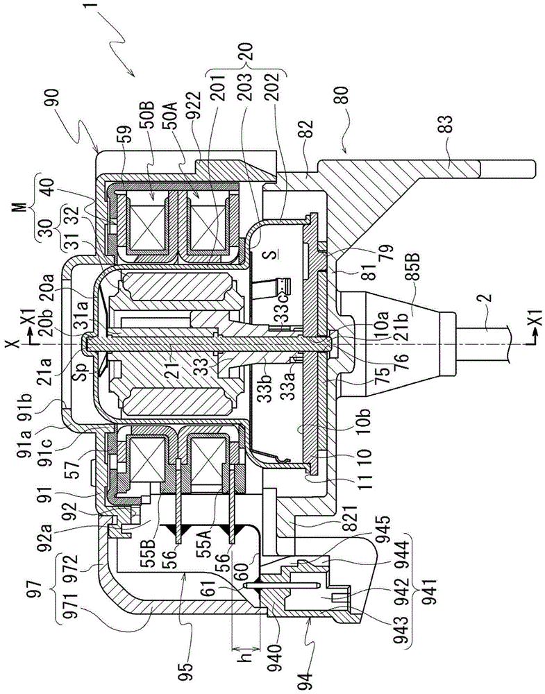
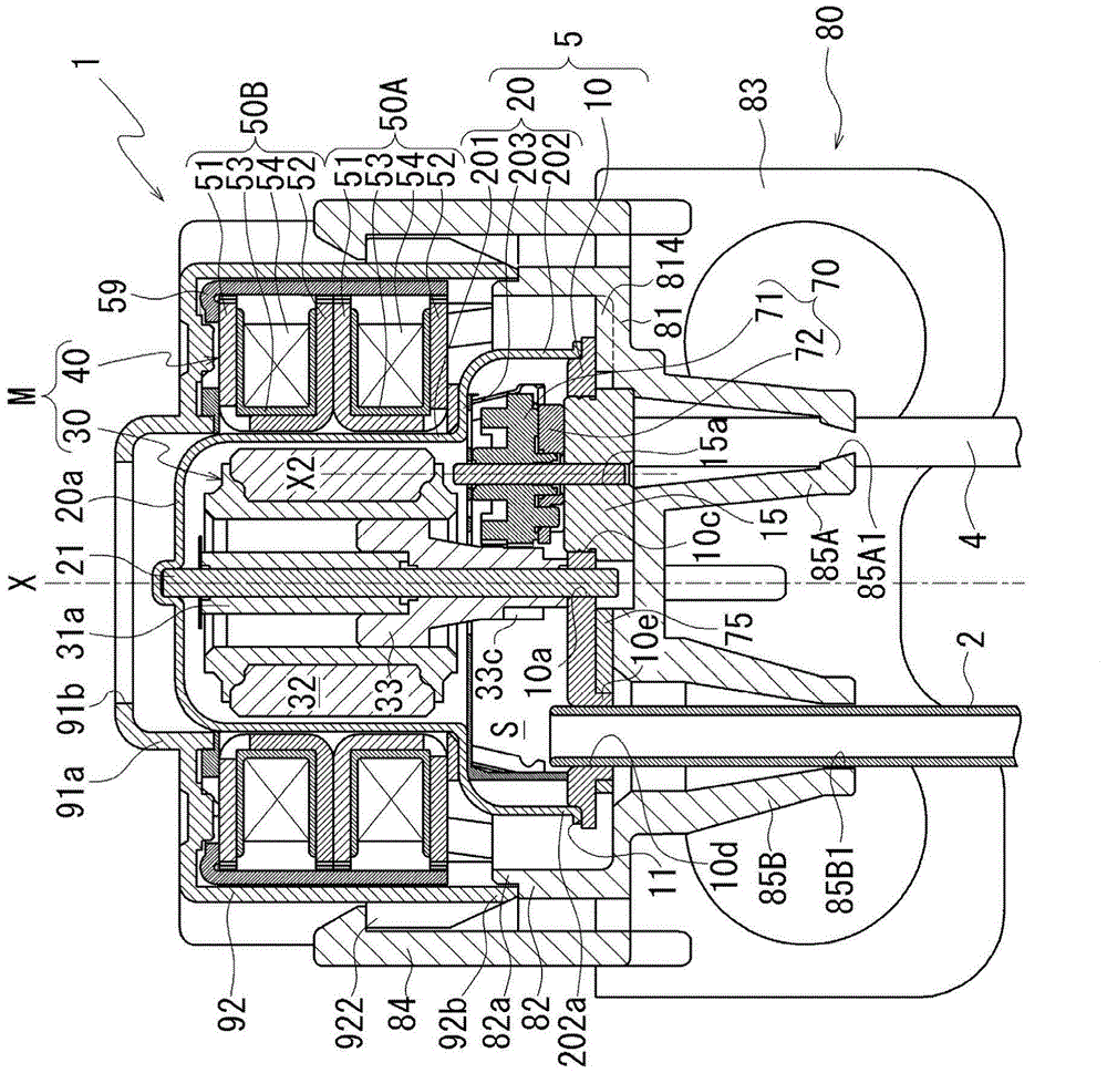
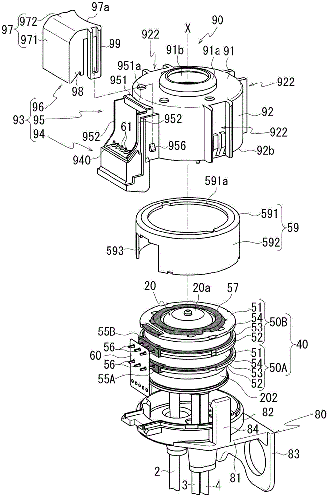
[0021] Hereinafter, embodiments of the present invention will be described in detail by taking the case where the present invention is applied to a valve element driving device (gear unit) of a valve device that opens and closes a refrigerant flow path of a refrigerator as an example, with reference to the drawings as appropriate. In addition, in each figure, the same code|symbol is attached|subjected to the common part, and overlapping description is abbreviate|omitted. In the following instructions, start with figure 1 The axis X of the rotating shaft of the rotor 30 of the shown spool driving device 1 is taken as a reference, and the rotor 30 side in the axial direction of the axis X is set as the upper side, and the fluid outlet pipes 3 and 4 sides are set as the lower side, and the valve is appropriately described. The positional relationship of each component of the core drive unit.

[0022] figure 1 It is a cross-sectional view of the valve body driving device 1 accor...


PUM


Abstract

The invention provides a valve body drive unit which can accurately position the circumferential position of the valve body drive unit even if an installation part is composed of a resin material. The valve body drive unit 1 uses a motor M to drive a valve body 72 arranged in a case 5, so that the flow path of a fluid introduced in the case 5 is switched. The valve body drive unit 1 is configured to have the following structure that the case 5 is formed by fixing a septum 20 of the bottomed cylindrical shape on a top surface 10b of a bottom plate part 10; a lower cover member 80 made of resin is provided with a fitting piece 814; the lower cover member 80 is used for fixing the case 5 at a fixing side part; and the fitting piece 814 is fitted with an opening part 75a of a reinforcement plate 75 of the bottom plate part 10 for limiting relative rotation between the case 5 and the lower cover member 80.

Description

technical field [0001] The invention relates to a valve core driving device. Background technique [0002] Patent Document 1 discloses a valve element driving device for switching between refrigerant gases. [0003] Patent Document 1: Japanese Patent Laid-Open No. 2001-116152 [0004] In the spool driving device disclosed in Patent Document 1, a mounting member for mounting the spool driving device to a fixed-side member is fitted to the outer periphery of a cylindrical case that accommodates the rotor portion. [0005] The mounting member has a plurality of elastic pieces pressed against the outer circumference of the housing, and the housing is held by the mounting member in a position positioned around the rotation axis of the rotor portion by the elastic pieces pressed against the outer circumference of the housing. [0006] Here, if the mounting member is made of a resin member, it is difficult to make the elastic piece have a strong elastic force, and the strength of...

Claims


Application Information

Patent Timeline
Patent Type & Authority Patents(China)
IPC IPC(8): F25B41/04
CPCF25B49/00F25B2600/25
Inventor 横江悟仓谷大树
Owner SANKYO SEIKI MFG CO LTD
Why Eureka
Try Eureka