Flywheel mold stripper

A technology of a feeder and a flywheel, which is applied in the field of feeders, can solve the problems of consuming a lot of manpower and time, inconvenient removal of the flywheel, and damage to castings, etc., and achieves the effect of saving financial resources.

Inactive Publication Date: 2015-06-03
LIANYUNGANG ZHUFU MACHINERY
View PDF0 Cites 1 Cited by
  • Summary
  • Abstract
  • Description
  • Claims
  • Application Information

AI Technical Summary

Problems solved by technology

[0002] In mold castings, since the castings will be partially attached to the mold after cooling, it will be troublesome to take out the castings, especially on the flywheel mold castings, because the material and volume of the flywheel are too large, it is very inconvenient to take out the flywheel after forming the casting. Generally, it is necessary to use external tools. The operation of general tools is complicated, requiring a lot of manpower and time, and sometimes damages the casting during the operation.

Method used


Image

  • Flywheel mold stripper
  • Flywheel mold stripper

Examples


Embodiment Construction

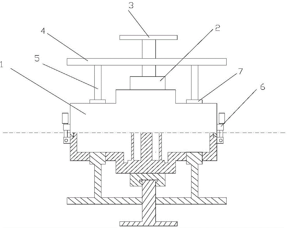
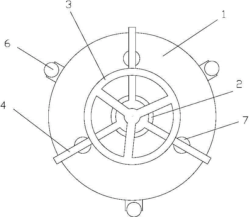
[0013] The figure shows a flywheel mold ejector, including a flywheel mold cover 1 and a material ejector. The flywheel mold cover is divided into an upper mold cover and a lower mold cover. , both the upper mold cover and the lower mold cover are provided with ejection holes, the ejection holes are evenly distributed on the flywheel mold cover in a circular shape, and the upper mold cover and the lower mold cover are equipped with ejectors, which include fixed The connecting block 2, the runner 3, the bracket 4, and the ejector rod 5 are composed of the fixed connecting block fixed at the center position outside the flywheel mold cover, and the runner is movably connected with the fixed connecting block through the fixed rotating rod, and the rotating rod is provided with threads , the runner can rotate freely, and the bracket is set as a horizontal bracket. The bracket is composed of a center piece and a support rod. The number of support rods is 3. The support rods are evenl...


PUM


Abstract

The invention discloses a flywheel mold stripper. The flywheel mold stripper comprises a flywheel mold cover and strippers, wherein the flywheel mold cover is arranged to comprise an upper mold cover and a lower mold cover; the upper mold cover and the lower mold cover are both provided with equal numbers of stripping holes and both provided with the strippers; the strippers comprise fixed connection blocks, rotating wheels, brackets and stripping rods; the fixed connection blocks are arranged at central positions on the outer sides of the flywheel mold cover; the rotating wheels are movably connected with the fixed connection blocks; the brackets are movably connected to the rotating wheels; certain ends of the stripping rods are fixedly arranged on the brackets; the other ends of the stripping rods are connected with the stripping holes. A casting in a mold can be quickly taken out with less labor by applying lever mechanics; the strippers of different sizes are designed according to different mold types to save financial, manpower and material resources.

Description

technical field [0001] The invention relates to a stripper, in particular to a stripper used on a flywheel mold. technical background [0002] In mold castings, since the castings will be partially attached to the mold after cooling, it will be troublesome to take out the castings, especially on the flywheel mold castings, because the material and volume of the flywheel are too large, it is very inconvenient to take out the flywheel after forming the casting. Generally, external tools are needed, and the operation of general tools is complicated, requiring a lot of manpower and time, and sometimes causing damage to the casting during the operation. Contents of the invention [0003] The invention aims at the deficiencies of the prior art, and provides a flywheel mold ejector with simple shortened manufacturing process, simple operation method and rapid discharge. [0004] In order to achieve the above object, the present invention is achieved through the following technic...

Claims


Application Information

Patent Timeline
Patent Type & Authority Applications(China)
IPC IPC(8): B22D29/08
CPCB22D29/08
Inventor 周可才
Owner LIANYUNGANG ZHUFU MACHINERY
Why Eureka
Try Eureka